77
8Insert the
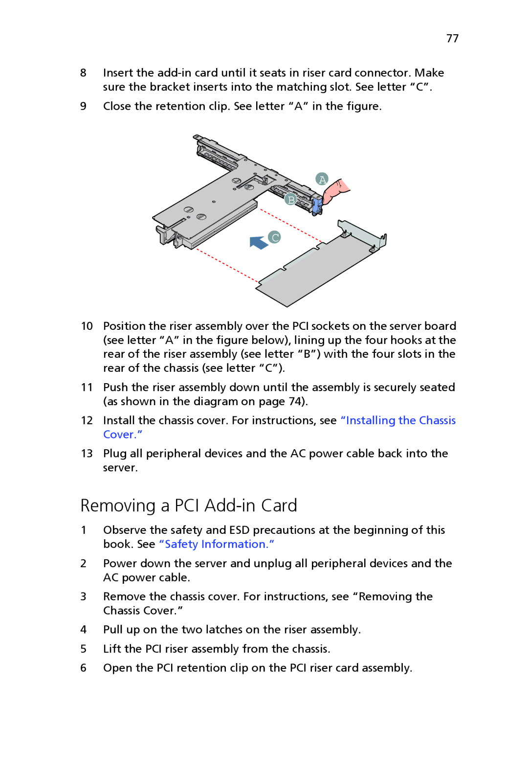
9Close the retention clip. See letter “A” in the figure.
A
B
![]() C
C
10Position the riser assembly over the PCI sockets on the server board (see letter “A” in the figure below), lining up the four hooks at the rear of the riser assembly (see letter “B”) with the four slots in the rear of the chassis (see letter “C”).
11Push the riser assembly down until the assembly is securely seated (as shown in the diagram on page 74).
12Install the chassis cover. For instructions, see “Installing the Chassis Cover.”
13Plug all peripheral devices and the AC power cable back into the server.
Removing a PCI Add-in Card
1Observe the safety and ESD precautions at the beginning of this book. See “Safety Information.”
2Power down the server and unplug all peripheral devices and the AC power cable.
3Remove the chassis cover. For instructions, see “Removing the Chassis Cover.”
4Pull up on the two latches on the riser assembly.
5Lift the PCI riser assembly from the chassis.
6Open the PCI retention clip on the PCI riser card assembly.