81
5Remove all
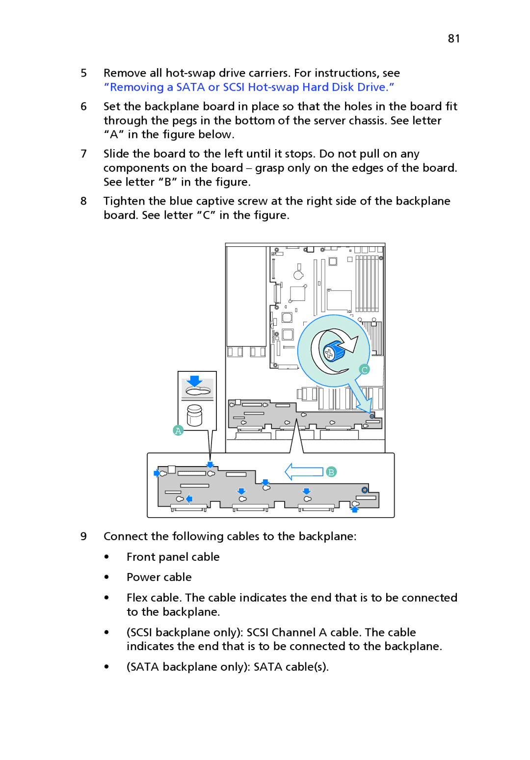
6Set the backplane board in place so that the holes in the board fit through the pegs in the bottom of the server chassis. See letter “A” in the figure below.
7Slide the board to the left until it stops. Do not pull on any components on the board – grasp only on the edges of the board. See letter “B” in the figure.
8Tighten the blue captive screw at the right side of the backplane board. See letter “C” in the figure.
A |
C |
![]() B
B
9Connect the following cables to the backplane:
•Front panel cable
•Power cable
•Flex cable. The cable indicates the end that is to be connected to the backplane.
•(SCSI backplane only): SCSI Channel A cable. The cable indicates the end that is to be connected to the backplane.
•(SATA backplane only): SATA cable(s).