Agilent Model 54835A/45A/46A Oscilloscopes
Service Policy
Trigger setup controls set mode and basic parameters
Ease of use with high performance
Display shows waveforms and graphical user interface
Measurements
Power
This Book
Contents
No Display Trouble Isolation
Contents
To check the keyboard To check the LEDs
To remove and replace the backlight inverter board
To remove and replace the floppy disk drive
Replaceable Parts
General Information
Instruments covered by this service guide
Oscilloscopes Covered by this Service Guide
Model Description
Accessories supplied
Accessories supplied
Options available
Options available
Option Number Description
Accessories available
Accessories available
Required when using 2 or more Agilent 1144A active probes
Agilent 1144A MHz Active Probe
Agilent
Specifications & characteristics
Specifications & characteristics
Acquisition
Specifications & characteristics Vertical
Offset Accuracy
Horizontal
Whichever is larger
Post-trigger
Specifications & characteristics Trigger
Measurements
Specifications & characteristics Display
Computer System/ Storage
CAT I and CAT II Definitions
Video Output
Rise Time figures are calculated from tr=.35/Bandwidth
Agilent Technologies 54835A/45A/46A general characteristics
Agilent Technologies 54835A/45A/46A general characteristics
General Characteristics
Agilent Technologies 54835A/45A/46A general characteristics
Recommended test equipment
Agilent Service software No substitution
Recommended test equipment
Agilent EPM Sensor 441A/Agilent 8482A
Preparing for Use
Preparing for Use
To inspect the instrument
To inspect the instrument
To connect power
To connect power
Three-wire Power Cable is Provided
To connect the mouse or other pointing device
To attach the optional trackball
To connect the mouse or other pointing device
To attach the optional trackball
To connect the keyboard
To connect to the LAN card
To connect the keyboard
To connect oscilloscope probes
To connect oscilloscope probes
To connect a printer
To connect a printer
To connect an external monitor
To connect the Gpib cable
To connect an external monitor
To tilt the oscilloscope upward for easier viewing
To tilt the oscilloscope upward for easier viewing
To power on the oscilloscope
To power on the oscilloscope
You Can Configure the Backlight Saver
Graphical Interface Enable Button
Press the Default Setup key on the front panel
To verify basic oscilloscope operation
Press the Autoscale key on the front panel
To clean the instrument
To clean the display monitor contrast filter
To clean the instrument
Testing Performance
See Also
Test Interval Dependencies
Let the Instrument Warm Up Before Testing
Clear Display
Averaging
Procedure
Enable the graphical interface
To test the dc calibrator
Connect the multimeter to the front panel Aux Out BNC
If the test fails
Set Aux Output to DC Set the output voltage
Selecting DC in the Calibration Dialog
To test input resistance
Input Resistance Equipment Setup
To test input resistance
25% accuracy Cables
To test voltage measurement accuracy
Specification
Connect the equipment
To test voltage measurement accuracy
Voltage Measurement Accuracy Equipment Setup
Acquisition Setup for Voltage Accuracy Measurement
Use the following table for steps 8 through
Scale Offset Supply Tolerance Limits
Select Channel 1 as the source for the Vavg measurement
Source Selection for Vavg Measurement
Set the scale from the table Set the offset from the table
To Set Vertical Scale and Position
Use the following table for steps 6 through
To test offset accuracy
To test offset accuracy
Volts/div Position Supply Tolerance Limits
To test offset accuracy
To test bandwidth
Specification Equivalent Time
Real Time
Equivalent Time Test
Calculate the response using the formula
Select Vamptd from the Voltage submenu of the Measure menu
Displayed. Note the Vamptd1 reading
MΩ, 500 MHz Test on 54835A, 54845A, and 54846A
Real Time Test
To test time measurement accuracy
Equivalent Time Mode Procedure
To test time measurement accuracy
Equivalent Time ≥16 averages
Waveform for Time Measurement Accuracy Check
Horizontal Setup for Equivalent Time Procedure
Source Selection for Delta Time Measurement
Acquisition Setup for Equivalent Time Procedure
For valid statistical data
Measurement Settings for Time Interval Measurement
New Measurement Settings for Delta Time Measurement
Measurement Definitions for Real Mode Procedure
Real-Time Mode Procedure
Click Close
To test trigger sensitivity
Acquisition Setup for Trigger Sensitivity Test
Set horizontal time/div to 5 ns/div
To test trigger sensitivity
Turn on Channel 1 and turn off all other channels
Setting the Markers for a 0.5 Division Reference
If a test fails
Procedure-Auxiliary Trigger Test
Page
Test Limits Results Vmax Vmin/5 =
Agilent Technologies 54835A/45A/46A Oscilloscope
Amplitude Input Channel Chan 4/Ext Resistance
Voltage Scale Coupling Supply Limits Channel
Channel 8 GSa/s
Realtime Channel 4 GSa/s
Channel 2 GSa/s
∆Time edge#101 Limits
Calibrating and Adjusting
Calibrating and Adjusting
Loading New Software
Let the Oscilloscope Warm Up Before Adjusting
Disconnect the oscilloscope power cord and remove the cover
To check the power supply
To check the power supply
Equipment Critical Specifications Recommended Model/Part
Supply Voltage Specification Limits
Power Supply Voltage Limits
Equipment Required
When to Use this Procedure
Flat-Panel Display Specifications
To check the flat panel display FPD
To check the flat panel display FPD
Starting the Screen Test
Click Start
Screen Test
Repeat steps 6 and 7 for all colors
To run the self calibration
To run the self calibration
Self calibration
Calibration time
Clear Cal Memory Protect to Run self calibration
Click Start, then follow the instructions on the screen
If calibration fails
Click here to start calibration
Page
Troubleshooting
Troubleshooting
Disconnect the instrument power cord and remove the cover
To install the fan safety shield
To install the fan safety shield
Installing the Fan Safety Shield
To troubleshoot the instrument
To troubleshoot the instrument
Primary Trouble Isolation
Primary Trouble Isolation Flowchart
Power-on Display Default Graphical Interface Disabled
Perform power-up
Primary Trouble Isolation
Check the display
Run oscilloscope self-tests
Check the front panel
Run the Knob and Key selftest and the LED selftest
No Display Trouble Isolation Flowchart
No Display Trouble Isolation
Remove the cabinet and install the fan safety shield
Check the fan connections
Sequence
Power supply indicator Isolation flowchart
Power-on
Completed its power-on test LEDs do not come on,
Configure the motherboard
Solenoids are preset Normal operating pattern
Power to the instrument.
Not, the problem may be with
Board video signals
Power Supply Trouble Isolation Flowchart
Check the power supply voltages
Power Supply Trouble Isolation
Power Supply Trouble Isolation
Approximate Resistance Values, Each Power Supply to Ground
Override the Remote Inhibit signal
Replace any shorted assembly
Power Supply Distribution
Power-up Sense Resistor Connection
Routing of +15 V Bias and Remote Inhibit Signals
Replace the power supply
Check +15 V Bias and Remote Inhibit cabling
Check for the oscilloscope display onscreen
To check probe power outputs
To check probe power outputs
Pin Supply +3V Offset Data Probe ID Ring Clk +12
Test Procedure
When you are finished, click Close
To check the keyboard
To check the keyboard
Re-assemble the instrument
Troubleshooting Procedure
To check the LEDs
To check the LEDs
Test by Rows
LED Test Screen
When you are finished, click Close
To check the motherboard, CPU, and RAM
To check the motherboard, CPU, and RAM
Messages Vary Slightly
To check the Svga display board video signals
To check the Svga display board video signals
Signal
Video Signals
To check the backlight inverter voltages
To check the backlight inverter voltages
Backlight Inverter Board Input Voltages Input Pin #
Backlight OFF Backlight on
Post Code Listing AMI Motherboard only
Post Code Listing AMI Motherboard only
Post Code Listing
Checkpoint Code Description
Unblocking command
Keyboard BAT command is issued
Color settings next
Next
2Eh
Clearing the memory below 1 MB for the soft reset next
Display memory read/write test next
2Fh
Command next
Keyboard reset command next
Winbios Setup next
After Winbios Setup next
Coprocessor text next
9Bh
9Ch
9Dh
To configure the motherboard jumpers and set up the Bios
To configure the motherboard jumpers and set up the Bios
Motherboard / floppy drive configurations Bios setup
To configure the motherboard jumpers and set up the Bios
To configure the motherboard jumpers and set up the Bios
Agilent Technologies Service Note Describes Upgrade Details
J46
Configuring the AMI Series 727 Motherboard Jumpers
J37, J39
Series 727 Motherboard Jumpers
MHz Clock Is Required
J2J21 J11 J12
J25J24 J37
To configure the AMI Series 727 Winbios Parameters
Press F1 to run the Winbios setup
Winbios Keyboard Commands
Do the following within the setup program
System Keyboard Absent
Do steps h-l only if Your System has 64 Mb RAM
Configuration Item Setting
Exit the Setup program, saving the changes you made
Load Optimal Defaults
Primary
Series 757 Rev C Motherboard Jumpers
Configuring the AMI Series 757 Motherboard for 200 MHz CPU
Pin
Do not Press F2
When to Do this Procedure
Series 757 System Bios Settings with 1.44 Mbyte floppy drive
Series 757 Rev D Motherboard Jumpers
Configuring the AMI Series 757 Motherboard for 300 MHz CPU
J14 J16
AMI Atlas-III PCI/ISA
Do the following within the setup program
Series 757 System Bios Settings with 120 Mbyte floppy drive
Core S1-1 S1-2 S1-3 S1-4
FIC VA-503A Motherboard
Off
Ratio S2-1 S2-2
Under the PnP/PCI Configuration, change these settings
Under the Power Management Setup, change these settings
Isolating Acquisition Problems
Under Integrated Peripherals, change these settings
To troubleshoot the acquisition system
To troubleshoot the acquisition system
Acquisition Trouble Isolation 1
Acquisition Trouble Isolation 2
Acquisition Trouble Isolation 3
To D Converter Failed
Return the Known Good Attenuator to Original Channel
Acquisition Trouble Isolation 4
Fiso failed
Temperature Sense failed
Probe Board failed
Offset DAC failed
Timer failed
Scroll Mode Counter failed
Interpolator failed
Timebase failed
To troubleshoot attenuator failures
To troubleshoot attenuator failures
Attenuator Click Test
Repeat steps 1 through 3 for the remaining input channels
Swapping Attenuators
Attenuator Connectivity Test
Attenuator Assembly Troubleshooting
Software Revisions
Enable the Graphical Interface
Select About Infiniium... from the Help Menu
Software Revisions
Page
Replacing Assemblies
Replacing Assemblies
To return the instrument to Agilent Technologies for service
Remove all accessories from the instrument
To remove and replace the cover
To remove and replace the cover
Cover Fasteners
To disconnect and connect Mylar flex cables
To disconnect and connect Mylar flex cables
To disconnect the cable
To reconnect the cable
Disconnect the power cable and remove the cover
To remove and replace the AutoProbe assembly
To remove and replace the AutoProbe assembly
Disconnecting W13
Pushing Out the AutoProbe Faceplate
Avoid Damage to the Ribbon Cable and Faceplate
To remove and replace the probe power and control assembly
To remove and replace the probe power and control assembly
Removing the Probe Power and Control Assembly
Avoid Interference with the Fan
To remove and replace the backlight inverter board
To remove and replace the front panel assembly
To remove and replace the backlight inverter board
Removing the Backlight Inverter Board
To remove and replace the front panel assembly
SMB Cable W18 and Comp Wire W19
Removing the BNC Nuts
Front Panel Side Screws
Disconnecting W16, W20, and the Backlight Cables
Front Panel Cover Plate Screws
Keep Long Screws Separate for Re-assembly
Removing the backlights
Removing the Cursor Keyboard
To remove and replace the acquisition board assembly
To remove and replace the acquisition board assembly
Removing the Acquisition Assembly
To remove and replace the LAN interface board
To replace the board, reverse the removal procedure
To remove and replace the LAN interface board
Removing the LAN Interface Board
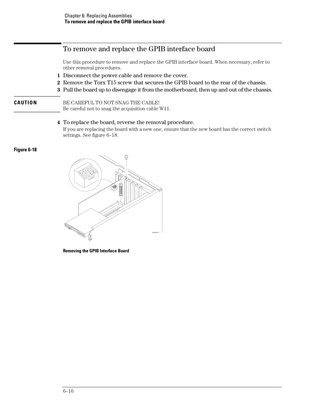
To remove and replace the Gpib interface board
To remove and replace the Gpib interface board
Removing the Gpib Interface Board
Removing the Scope Interface and Svga Display Boards
Disconnect these cables from the Svga display board
To separate the scope interface board and Svga display board
To separate the scope interface board and Svga display board
To replace the card, reverse the removal procedure
To remove and replace the Option 200 sound card
To remove and replace the Option 200 sound card
To remove and replace the hard disk drive
To remove and replace the hard disk drive
Removing the Hard Disk Drive
To remove and replace the motherboard
To remove and replace the floppy disk drive
To remove and replace the floppy disk drive
Removing the Floppy Disk Drive Screws
Disconnect these cables from the motherboard
To remove and replace the motherboard
Removing the Motherboard Torx Screws
To remove and replace the motherboard
To remove and replace the power supply
To remove and replace the power supply
Removing Power Supply Cables
To remove and replace the fan
To install the fan, reverse this procedure
To remove and replace the fan
Removing Fan Fasteners
To remove and replace the CPU
To remove and replace the CPU
Removing the CPU
To remove and replace RAM SIMMs or Sdram DIMMs
To remove and replace RAM SIMMs or Sdram DIMMs
Removing and replacing SIMMs on the AMI motherboard
Removing RAM SIMMs
To remove and replace an attenuator
To remove and replace an attenuator
Do Not Remove the Attenuators from the Acquisition Board
Removing an Attenuator
If You Permanently Replace Parts
To reset the attenuator contact counter
To reset the attenuator contact counter
Self Test
Attenuator Relay Actuations Setup
Attenuator Channel box, select the channel you are changing
Repeat for each channel you need to change
To remove and replace an acquisition hybrid
To remove and replace an acquisition hybrid
To remove the acquisition hybrid
Do not USE Excessive Force
To replace the acquisition hybrid
Removing the Hybrid Connector
Hybrid Connector
Replaceable Parts
Listed Parts
Ordering Replaceable Parts
Unlisted Parts
Direct Mail Order System
Power Cables and Plug Configurations
Power Cables and Plug Configurations
Plug Type Cable Plug Description Length Color Country In/cm
Exploded Views
Exploded Views
MP61 MP17 MP62 or MP63 MP15 and MP49
Front Frame and Front Panel
Fan and Acquisition Assembly
Power Supply and PC Motherboard
A10 MP57
H12 H24 H25 MP55 MP60 H11
Exploded Views
A4A1W24/25 A4A4
Exploded Views
Exploded Views
FIC VA-503A Motherboard for PC Motherboard Configuration
W17W20 A15 W14 W11 A19 W16 A14 W24/25 W27 W22 A4A1
H23 A4A2
Exploded Views
MP14 MP52 MP70 MP72
Sleeve and Accessory Pouch
MP12
H10 MP20 MP13 H19 H26 MP19
Attenuator Assembly
Replaceable Parts List
Replaceable Parts List
QTY
Agilent Part Des Number
DRAM-SIMM 2MX32 8 MB Simm
DRAM-DIMM 16MX32 64 MB Dimm
Fans
Cables
Display BD. Jumper
Page
Theory of Operation
Theory of Operation
Power Supply Assembly
FPD Monitor Assembly
Block-Level Theory
Front Panel
Acquisition System
Disk Drives
Attenuators
Probe Power and Control
Svga Display Card
Gpib Interface Card
Acquisition Block Diagram
Acquisition Theory
Attenuator Theory
Attenuator Theory
Acquisition Board
Acquisition Theory
Scope Interface Board
Acquisition Modes
Page
Manufacturer’s Name
Manufacturer’s Address
Supplementary Information
Product Regulations
Restricted Rights Legend
Product Warranty