AT-CV5000 Media Converter Chassis Installation Guide
8-Pin Mini-DIN Console Port Pinouts
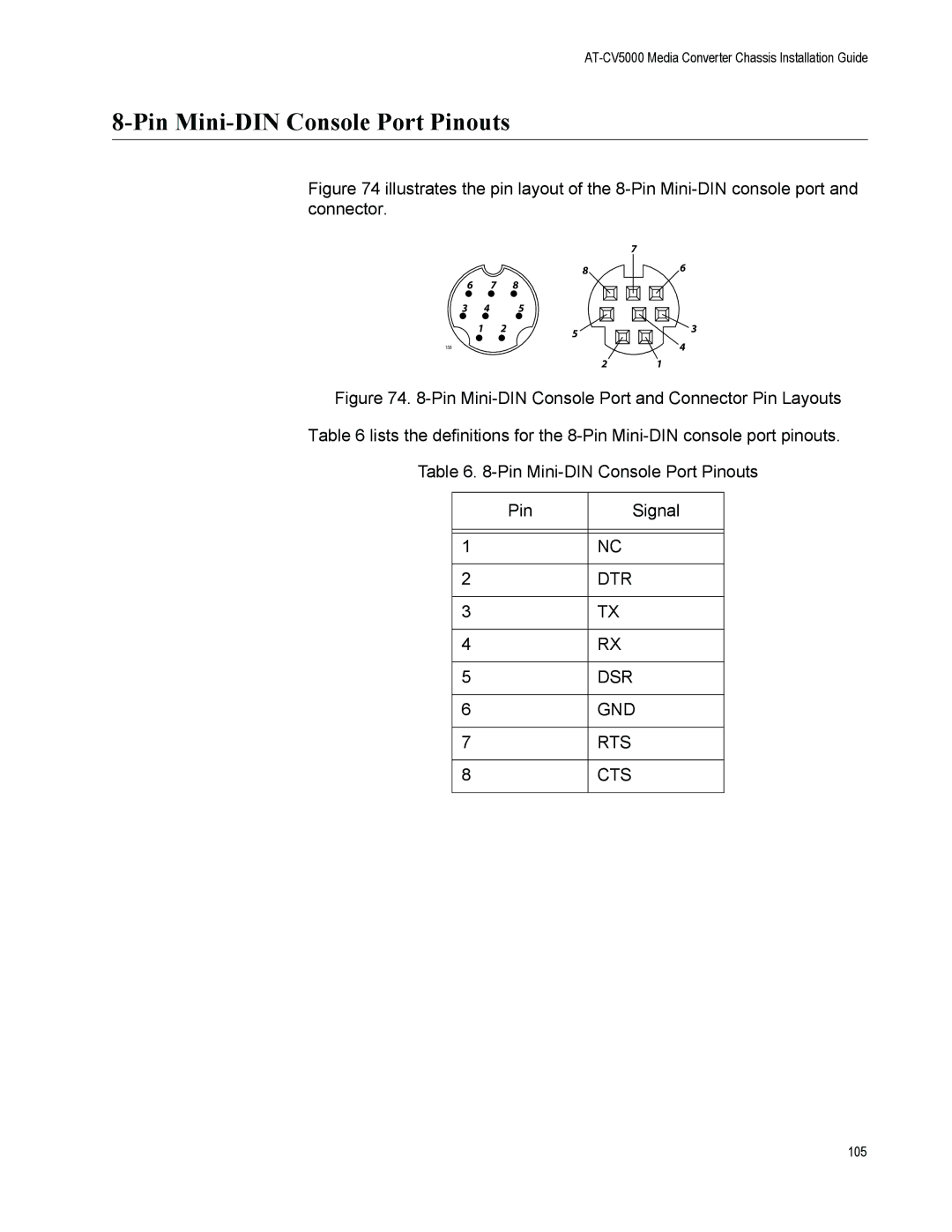
Figure 74 illustrates the pin layout of the 8-Pin Mini-DIN console port and connector.
8
6 | 7 |
| 8 |
3 | 4 |
| 5 |
| 1 | 2 | 5 |
|
|
|
158
2
7
6
3
4
1
Figure 74. 8-Pin Mini-DIN Console Port and Connector Pin Layouts Table 6 lists the definitions for the 8-Pin Mini-DIN console port pinouts.
Table 6. 8-Pin Mini-DIN Console Port Pinouts
Pin | Signal |
|
|
|
|
1 | NC |
|
|
2 | DTR |
|
|
3 | TX |
|
|
4 | RX |
|
|
5 | DSR |
|
|
6 | GND |
|
|
7 | RTS |
|
|
8 | CTS |
|
|
105