Chapter 3: Working with Line Cards and other Modules
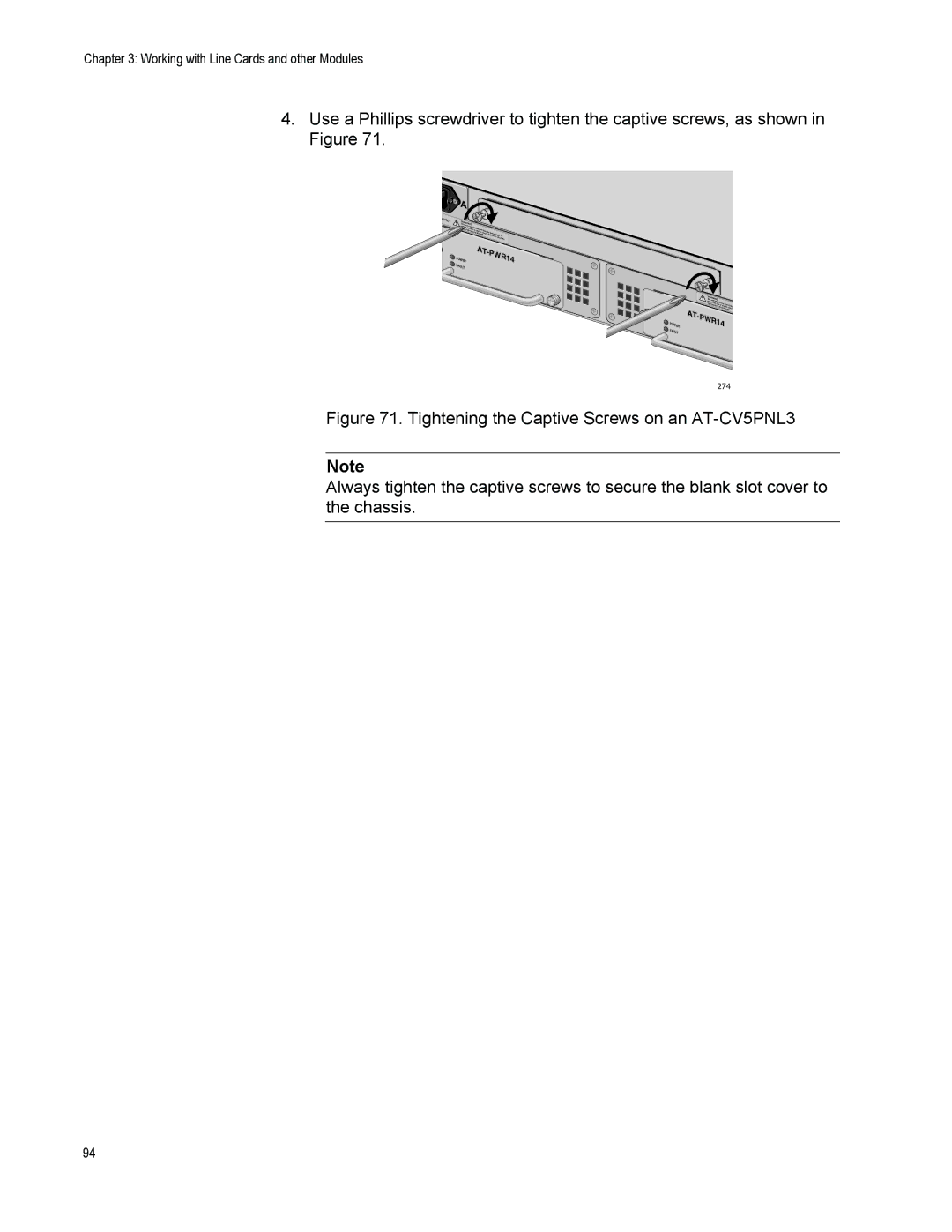
4.Use a Phillips screwdriver to tighten the captive screws, as shown in Figure 71.
4 | 0VAC~ |
|
A |
|
|
|
| |
WAR |
|
|
|
|
|
This uniNINGt |
|
|
|
| |
reduce | might |
|
|
| |
inputs | the risk have m |
|
| ||
| before | of elec ore than | one po |
| |
|
| ser | tric sh |
| |
|
|
| vicing unit. ock, discower input. |
| |
|
|
|
| nnect all | To |
|
|
|
|
| power |
![]() POWER FAULT
POWER FAULT
AT-PWR14
POWER FAULT
WAR | NING | |
This unit | might | |
reduce |
| |
inputs | the risk ofhave more | |
| before servelectric shthan o | |
AT- |
| icing unit. ock |
|
| |
PWR14 | ||
274
Figure 71. Tightening the Captive Screws on an AT-CV5PNL3
Note
Always tighten the captive screws to secure the blank slot cover to the chassis.
94