Chapter 1: Overview
Fan Modules
The
Caution
The
Note
The
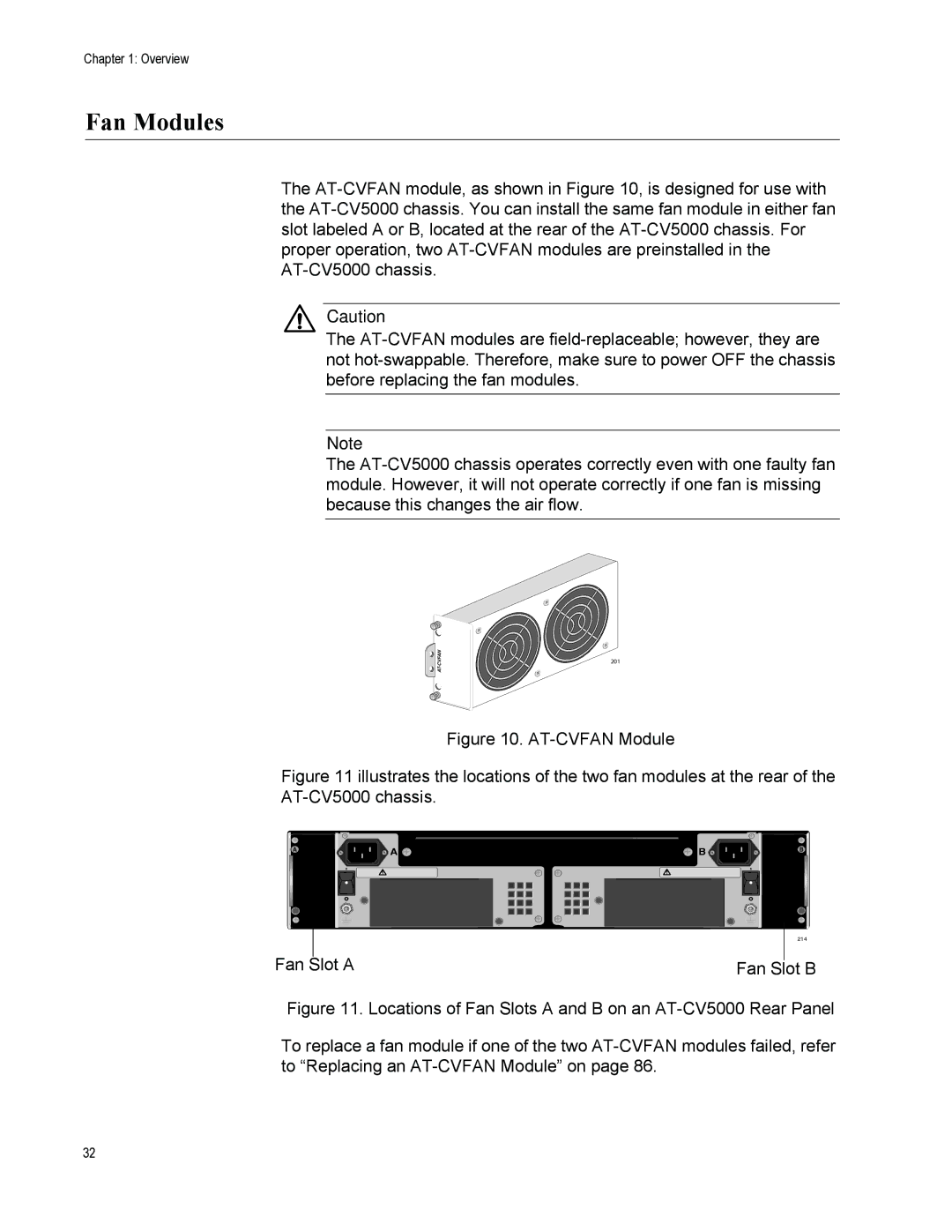
201
Figure 10. AT-CVFAN Module
Figure 11 illustrates the locations of the two fan modules at the rear of the AT-CV5000 chassis.
REAR EXP. SLOT
A![]() A
A
| WARNING | |
This unit might have more than one power input. To | ||
| reduce the risk of electric shock, disconnect all power | |
|
| inputs before servicing unit. |
Fan Slot A
B | B |
| |
WARNING | |
This unit might have more than one power input. To | |
reduce the risk of electric shock, disconnect all power | |
inputs before servicing unit. |
|
214
Fan Slot B
Figure 11. Locations of Fan Slots A and B on an AT-CV5000 Rear Panel
To replace a fan module if one of the two AT-CVFAN modules failed, refer to “Replacing an AT-CVFAN Module” on page 86.
32