Chapter 3: Working with Line Cards and other Modules
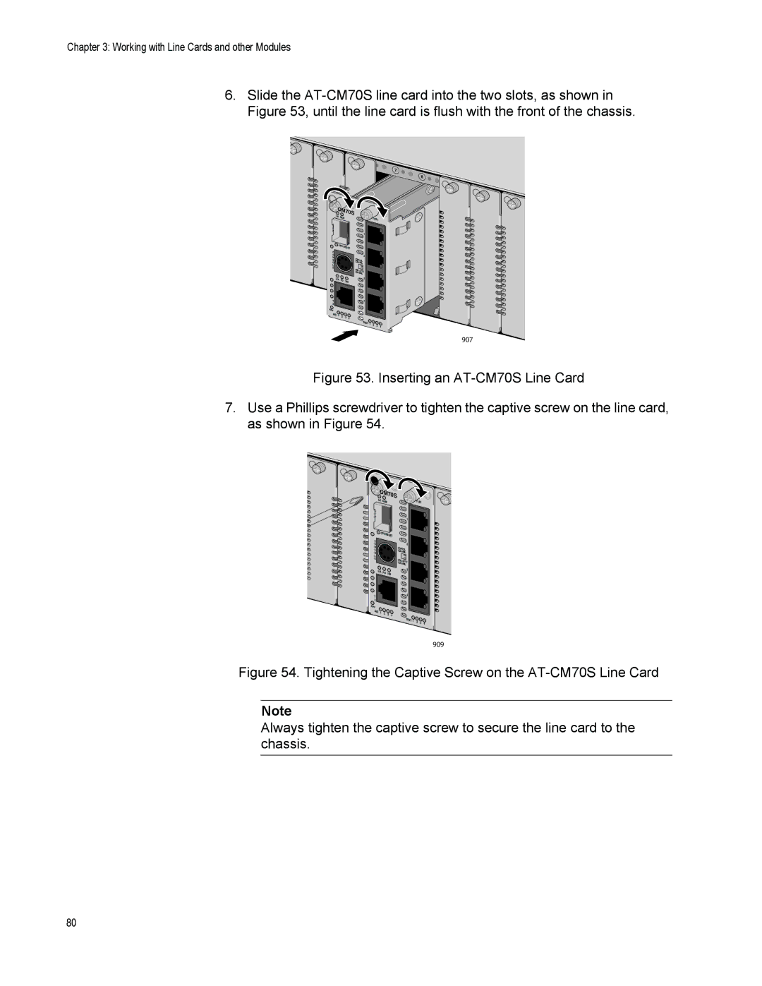
6.Slide the
7
9 ![]() 10
10
AT- |
|
CM70S |
|
LK |
|
OAM | T1/E1 |
S |
|
F |
|
P | 1 |
| |
CPU |
|
RESET |
|
C O N S O L E
2
![]() RCL NML
RCL NML
![]() LOTC NML
LOTC NML
L/A FD
![]() 3 100
3 100
T | 4 |
X |
|
RDY
AIS | 1 | 2 | 3 |
|
| 4 | |||
|
|
|
TEST | 1 | 2 | 3 |
|
| 4 | |||
|
|
|
907
Figure 53. Inserting an AT-CM70S Line Card
7.Use a Phillips screwdriver to tighten the captive screw on the line card, as shown in Figure 54.
AT- |
|
CM70S |
|
LK | T1/E1 |
OAM | |
S |
|
F |
|
P | 1 |
|
![]() CPU RESET
CPU RESET
C O N S O L E
2
![]() RCL NML
RCL NML
![]() LOTC NML
LOTC NML
L/A | FD | 3 | |
100 | |||
|
|
T![]() 4
4
X
RDY
AIS | 1 | 2 | 3 | 4 |
|
|
|
TEST | 1 | 2 | 3 | 4 |
|
|
|
909
Figure 54. Tightening the Captive Screw on the AT-CM70S Line Card
Note
Always tighten the captive screw to secure the line card to the chassis.
80