AT-CV5000 Media Converter Chassis Installation Guide
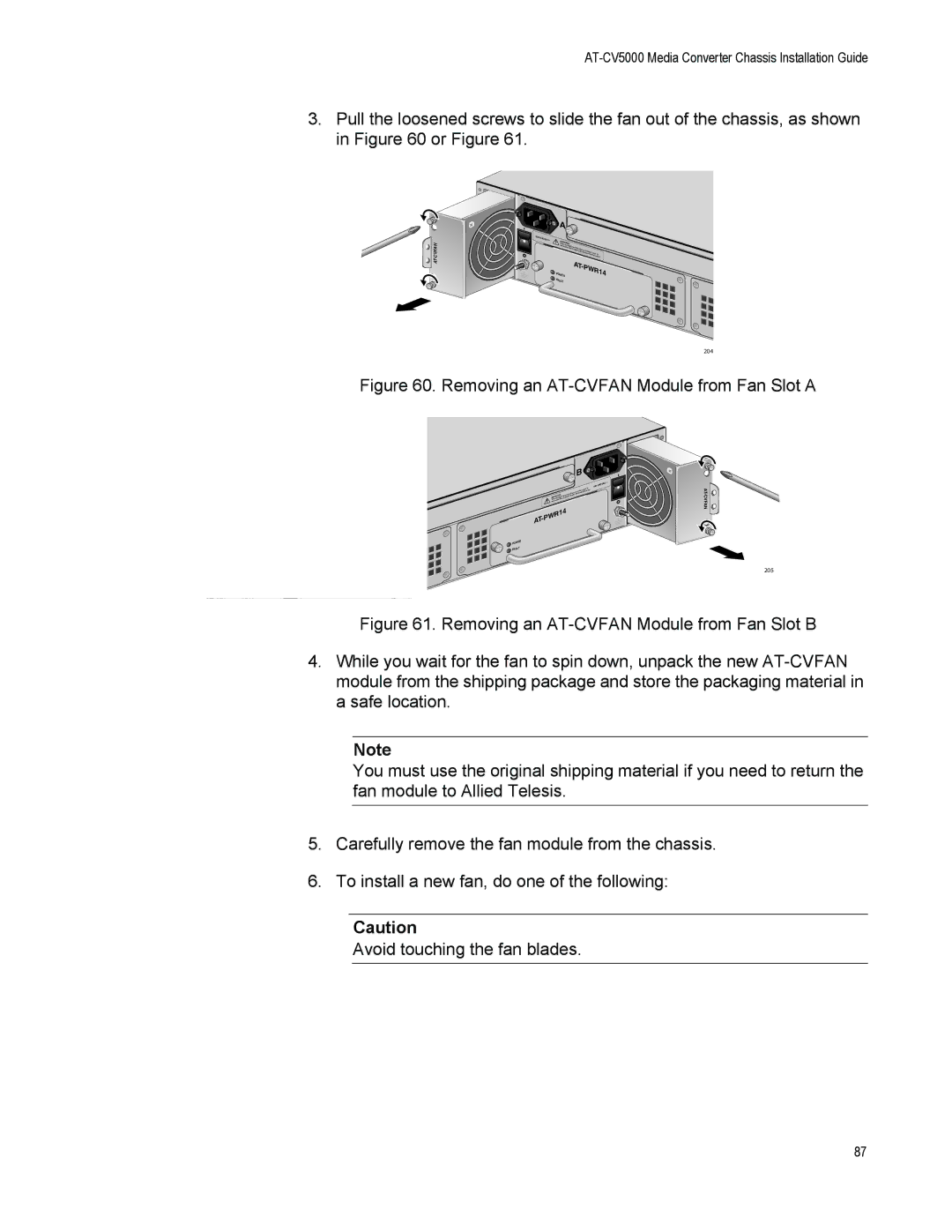
3.Pull the loosened screws to slide the fan out of the chassis, as shown in Figure 60 or Figure 61.
A
|
| A |
|
|
|
|
| 100- |
|
|
|
|
|
| 240VAC~ | WARNING |
|
|
| |
|
|
|
|
| ||
| This unit |
|
|
|
| |
| reduce | might |
|
|
| |
|
|
| the risk have | more than |
| |
|
|
| of |
|
| |
|
|
|
| electric shock,one power |
| |
|
|
|
|
| disconnectinput. To | |
|
|
|
|
| all power | |
|
|
|
| AT- |
| |
|
| POWER |
|
| PW | R14 |
|
| FAULT |
|
|
|
|
204
Figure 60. Removing an AT-CVFAN Module from Fan Slot A
A ![]() FAN
FAN
|
| A |
|
| |
0VAC | ~ | |
|
| AT |
B |
|
|
0VAC | ~ | |
| ||
TWARhis unNINGthit me risighkt ohfaveelemctoricresthhoacnko, ndeispcoownneercint paulltp. Toower |
|
|
reduce |
|
|
AT-PWR14
POWE | R |
T |
|
FAUL |
|
B
![]()
![]()
205
Figure 61. Removing an AT-CVFAN Module from Fan Slot B
4.While you wait for the fan to spin down, unpack the new
Note
You must use the original shipping material if you need to return the fan module to Allied Telesis.
5.Carefully remove the fan module from the chassis.
6.To install a new fan, do one of the following:
Caution
Avoid touching the fan blades.
87