Chapter 3: Working with Line Cards and other Modules
Installing an
AT-CV5PNL2
Blank Slot Cover
The
To install an
1.Remove the
Note
You must use the original package if you need to return the unit to Allied Telesis.
2.Select the power supply slot in the
3.Align the back edge of the blank slot cover with the alignment guides located inside the slot.
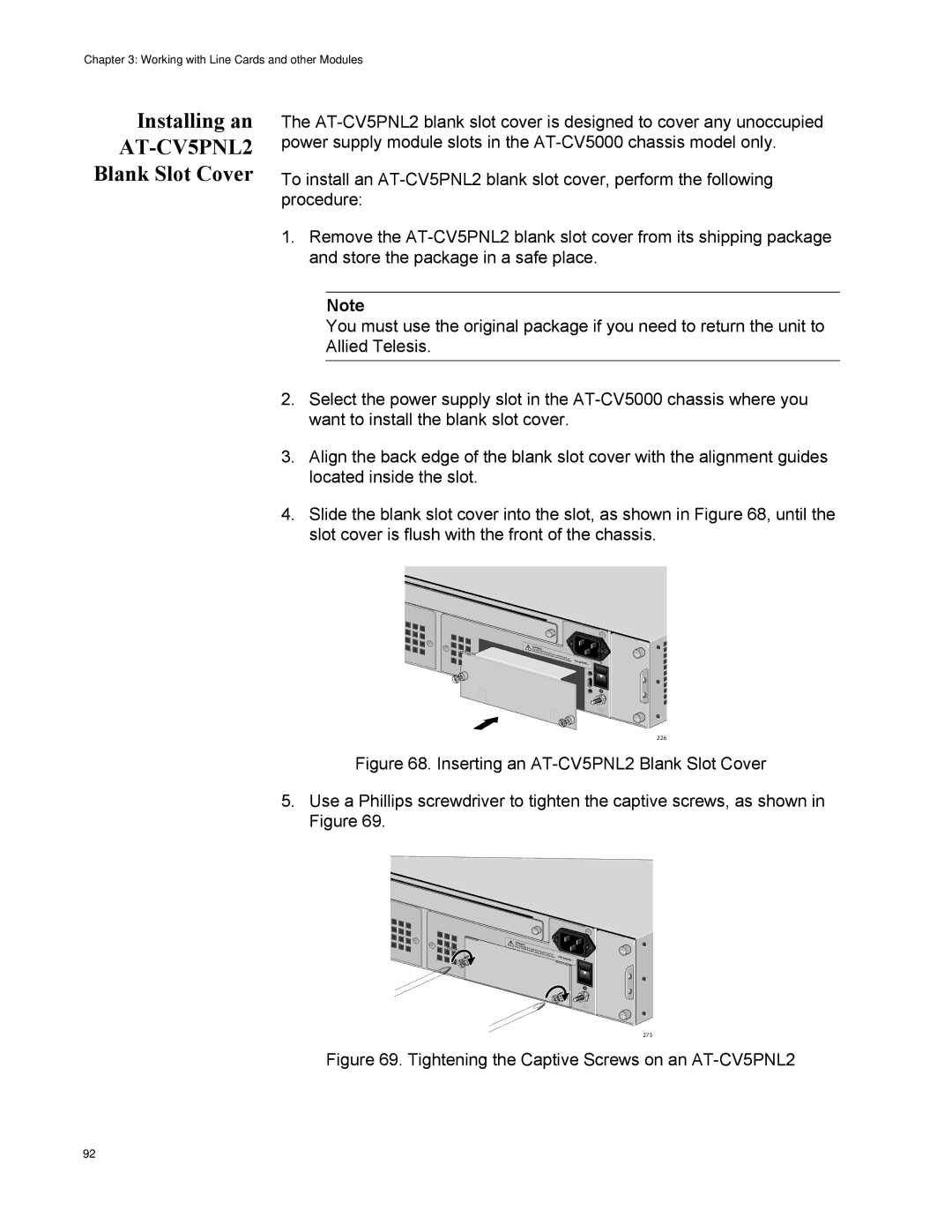
4.Slide the blank slot cover into the slot, as shown in Figure 68, until the slot cover is flush with the front of the chassis.
WARNINGThis unit |
|
|
reduce thme rigishkt ohfaveelemctorircesthhan one po |
|
|
ock, discownneercint paulltp. Toower | VAC~ | |
|
|
226
Figure 68. Inserting an AT-CV5PNL2 Blank Slot Cover
5.Use a Phillips screwdriver to tighten the captive screws, as shown in Figure 69.
WARNINGThis unit |
|
|
reduce thme ight have |
|
|
risk of elemore than |
|
|
ctric shocko, ndeispcower input. | To |
|
onnect all | 100- | |
| power | |
|
| 240VAC~ |
273
Figure 69. Tightening the Captive Screws on an AT-CV5PNL2
92