Chapter 1: Overview
Front and Rear Panel Components
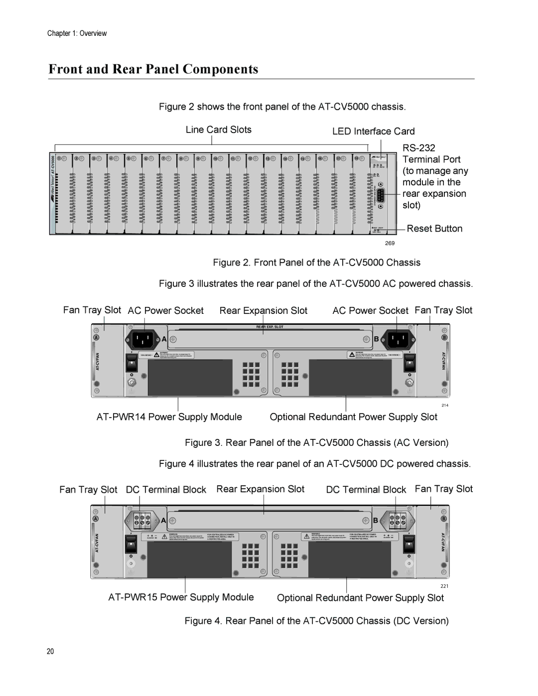
Figure 2 shows the front panel of the AT-CV5000 chassis.
|
|
|
|
|
|
|
|
| Line Card Slots |
|
|
|
| LED Interface Card | ||||||
|
|
|
|
|
|
|
|
|
|
|
|
|
|
|
|
|
|
|
| |
1 | 2 | 3 | 4 | 5 | 6 | 7 | 8 | 9 | 10 | 11 | 12 | 13 | 14 | 15 | 16 | 17 | 18 |
| Terminal Port | |
|
|
|
|
|
|
|
|
|
|
|
|
|
|
|
|
| ||||
|
|
|
|
|
|
|
|
|
|
|
|
|
|
|
|
| RDY | FLT MASTER | (to manage any | |
|
|
|
|
|
|
|
|
|
|
|
|
|
|
|
|
| FAN1 |
| ||
|
|
|
|
|
|
|
|
|
|
|
|
|
|
|
|
| PS1 |
| ||
|
|
|
|
|
|
|
|
|
|
|
|
|
|
|
|
| ||||
|
|
|
|
|
|
|
|
|
|
|
|
|
|
|
|
|
| RDY |
| module in the |
|
|
|
|
|
|
|
|
|
|
|
|
|
|
|
|
|
| REAR EXP. |
| |
|
|
|
|
|
|
|
|
|
|
|
|
|
|
|
|
|
|
| rear expansion | |
|
|
|
|
|
|
|
|
|
|
|
|
|
|
|
|
|
| CONSOLE |
| |
|
|
|
|
|
|
|
|
|
|
|
|
|
|
|
|
|
|
| slot) | |
|
|
|
|
|
|
|
|
|
|
|
|
|
|
|
|
|
|
|
| |
|
|
|
|
|
|
|
|
|
|
|
|
|
|
|
|
|
| RESET LINE/EXP | Reset Button | |
|
|
|
|
|
|
|
|
|
|
|
|
|
|
|
|
|
| |||
|
|
|
|
|
|
|
|
|
|
|
|
|
|
|
|
|
|
|
| 269 |
Figure 2. Front Panel of the | |
Figure 3 illustrates the rear panel of the | |
Fan Tray Slot AC Power Socket Rear Expansion Slot | AC Power Socket Fan Tray Slot |
A 
CVFAN-AT
REAR EXP. SLOT
![]() A
A ![]()
| WARNING |
This unit might have more than one power input. To | |
reduce the risk of electric shock, disconnect all power |
inputs before servicing unit.
B ![]()
WARNING
This unit might have more than one power input. To~ reduce the risk of electric shock, disconnect all power
inputs before servicing unit.
B ![]()
|
|
|
|
|
|
|
| 214 |
|
|
|
|
|
|
| ||
| Supply Module | Optional Redundant |
| Power Supply Slot | ||||
|
| |||||||
Figure 3. Rear Panel of the AT-CV5000 Chassis (AC Version)
Figure 4 illustrates the rear panel of an AT-CV5000 DC powered chassis.
Fan Tray Slot DC Terminal Block Rear Expansion Slot | DC Terminal Block Fan Tray Slot |
A
![]() A
A ![]()
WARNING |
This unit might have more than one power input. To |
FOR CENTRALIZED DC POWER CONNECTION, INSTALL ONLY IN
WARNING
This unit might have more than one power input. To
![]() B
B ![]()
FOR CENTRALIZED DC POWER
CONNECTION, INSTALL ONLY IN
B
AT
AT-CVFAN
reduce the risk of electric shock, disconnect all power | |
| inputs before servicing unit. |
A RESTRICTED AREA.
reduce the risk of electric shock, disconnect all power inputs before servicing unit.
A RESTRICTED AREA.
|
|
|
|
|
|
| 221 |
|
|
|
|
|
| ||
| Supply Module |
|
|
|
|
| |
| Optional Redundant Power Supply Slot | ||||||
Figure 4. Rear Panel of the AT-CV5000 Chassis (DC Version)
20