AT-CV5000 Media Converter Chassis Installation Guide
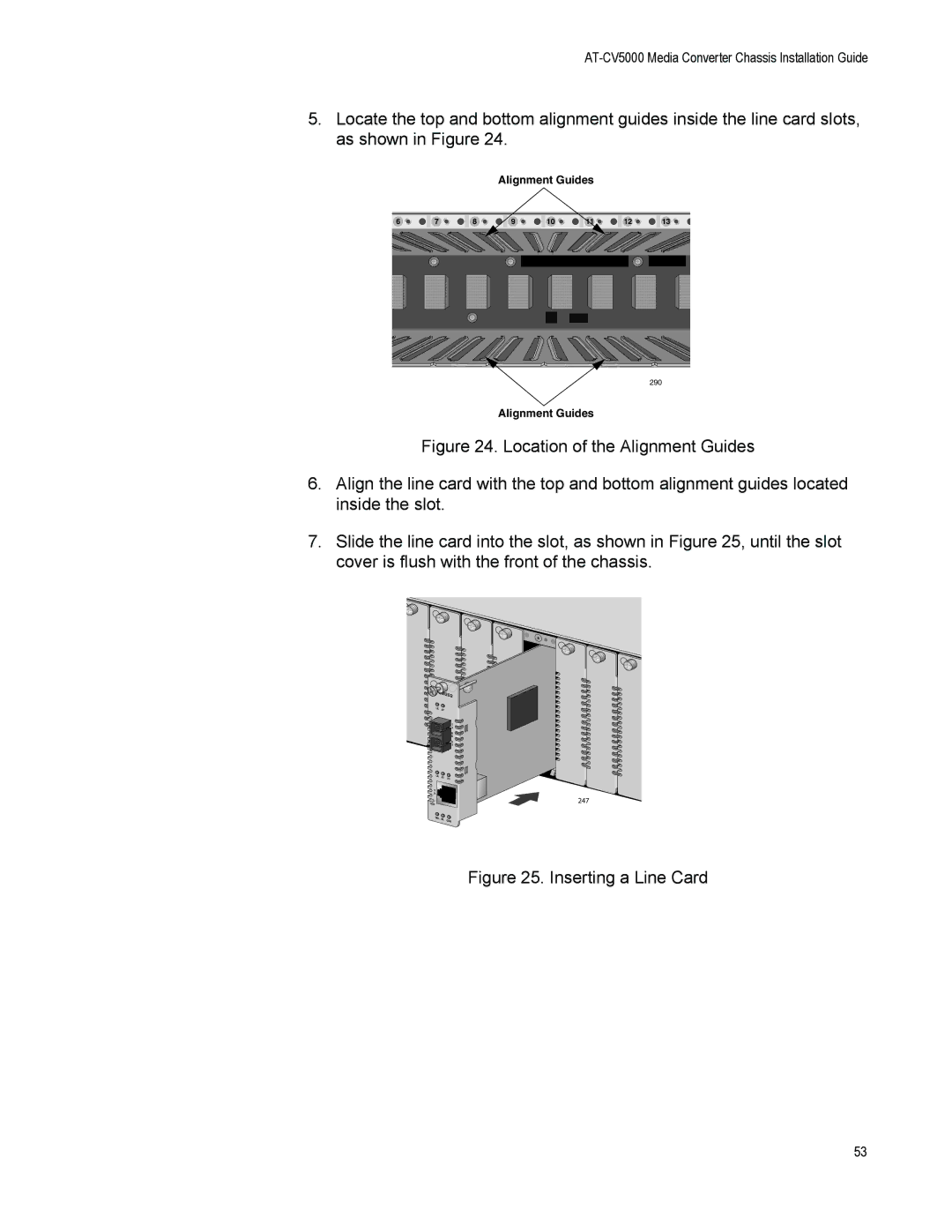
5.Locate the top and bottom alignment guides inside the line card slots, as shown in Figure 24.
Alignment Guides
6 | 7 | 8 | 9 | 10 | 11 | 12 | 13 |
290
Alignment Guides
Figure 24. Location of the Alignment Guides
6.Align the line card with the top and bottom alignment guides located inside the slot.
7.Slide the line card into the slot, as shown in Figure 25, until the slot cover is flush with the front of the chassis.
7
8
M202 |
LK | AT |
|
|
| T |
|
| X |
|
| M |
|
| M |
|
| R |
|
| X |
LK | AT | FD |
| ||
T |
|
|
X |
|
|
RDY |
|
|
SML | ML | OAM |
9 |
10 |
247
Figure 25. Inserting a Line Card
53
