AT-CV5000 Media Converter Chassis Installation Guide
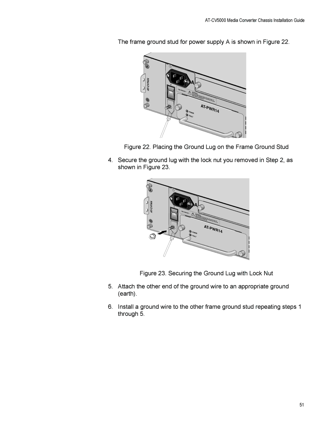
The frame ground stud for power supply A is shown in Figure 22.
A ![]()
|
| A |
|
|
|
|
|
|
|
| |
100- |
|
|
|
|
|
|
|
|
|
|
|
240 |
|
|
|
|
|
|
|
|
|
|
|
VAC | W |
|
|
|
|
|
|
|
|
| |
| ~ |
|
|
|
|
|
|
|
|
| |
|
| ARNINGis un |
|
|
|
|
|
| |||
|
| Th |
| it |
|
|
|
|
|
|
|
|
| redu |
|
|
|
|
|
|
|
| |
|
|
| ce thmight h |
|
|
|
| ||||
|
| inputs | e risk | ave | more |
|
| ||||
|
|
|
| befo | re |
| of e |
| than o |
| |
|
|
|
|
|
|
| lectric |
| |||
|
|
|
|
|
| servicing unshock,nde power | |||||
|
|
|
|
|
|
|
|
|
| it. | isconnecint put. To |
|
|
|
|
|
|
|
|
|
|
| all p |
|
|
|
|
|
|
|
|
|
|
| ower |
|
|
|
|
|
|
|
|
| AT- | ||
|
| POW |
|
|
|
|
|
|
|
| PWR14 |
|
| ER |
|
|
|
|
|
|
|
|
|
|
| FA |
|
|
|
|
|
|
|
|
|
|
| ULT |
|
|
|
|
|
|
|
|
|
Figure 22. Placing the Ground Lug on the Frame Ground Stud
4.Secure the ground lug with the lock nut you removed in Step 2, as shown in Figure 23.
A ![]()
|
| A |
|
|
|
|
|
|
|
|
|
|
| |
100- |
|
|
|
|
|
|
|
|
|
|
|
|
|
|
240 |
|
|
|
|
|
|
|
|
|
|
|
|
|
|
VAC | W |
|
|
|
|
|
|
|
|
|
|
| ||
| ~ |
|
|
|
|
|
|
|
|
|
|
| ||
|
| ThisARNING |
|
|
|
|
|
|
|
|
| |||
|
|
| unit | might |
|
|
|
|
|
|
|
| ||
|
| reduce |
|
|
|
|
|
|
|
|
| |||
|
| inputs | the risk have | more |
|
|
|
|
| |||||
|
|
|
| before | of |
| than one |
|
|
| ||||
|
|
|
|
|
| se |
| electric | power |
|
| |||
|
|
|
|
|
|
| rvicing | shock, |
| input. |
| |||
|
|
|
|
|
|
|
|
| unit. |
|
| To | ||
|
|
|
|
|
|
|
|
|
|
| disconnect all | |||
|
|
|
|
|
|
|
|
|
|
|
|
|
| power |
|
|
|
|
|
|
|
|
| AT- | PWR14 | ||||
|
| POW | ER |
|
|
|
|
|
|
| ||||
|
|
|
|
|
|
|
|
|
|
|
|
|
| |
|
| FA |
|
|
|
|
|
|
|
|
|
|
|
|
|
| ULT |
|
|
|
|
|
|
|
|
|
|
| |
Figure 23. Securing the Ground Lug with Lock Nut
5.Attach the other end of the ground wire to an appropriate ground (earth).
6.Install a ground wire to the other frame ground stud repeating steps 1 through 5.
51