AT-CV5000 Media Converter Chassis Installation Guide
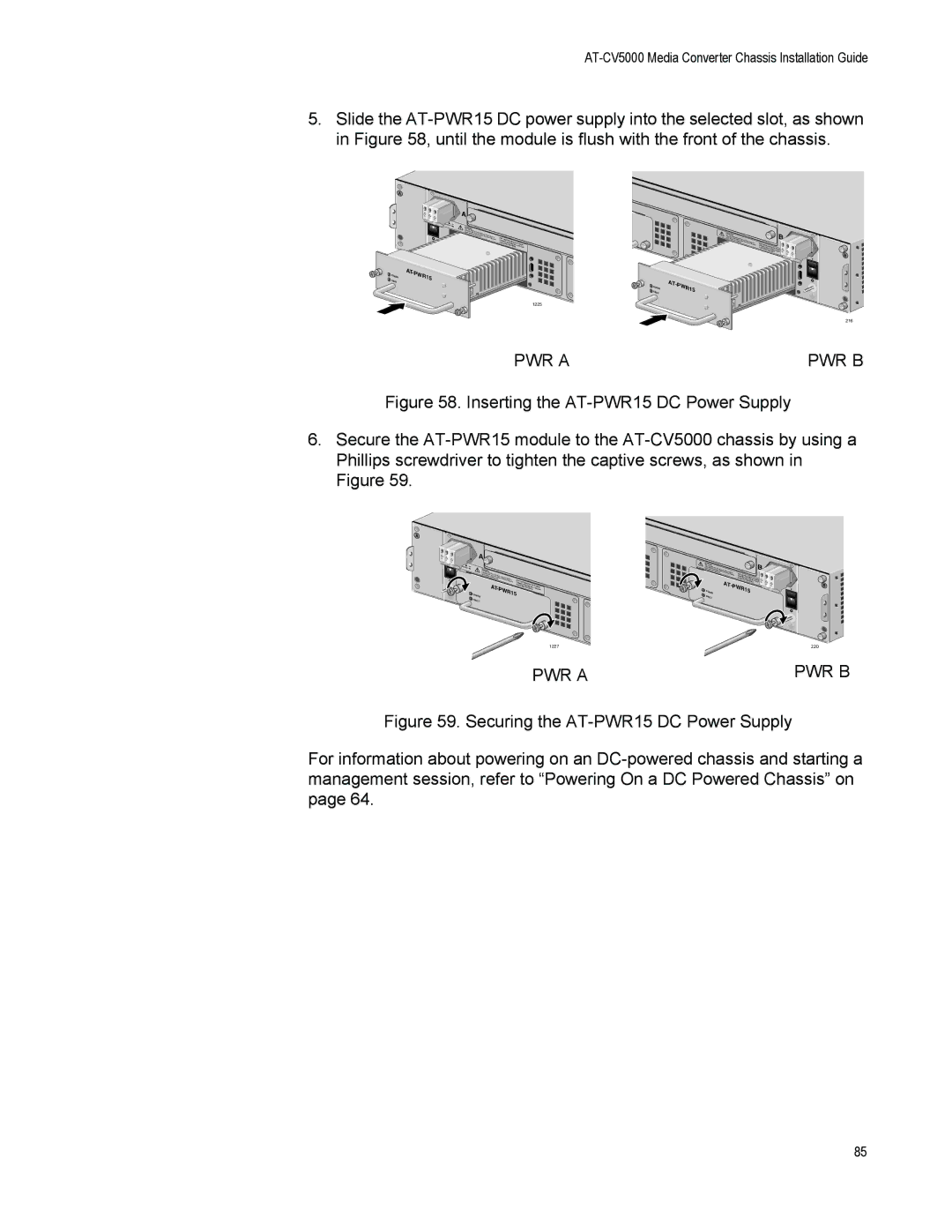
5.Slide the
A
|
|
| A |
|
|
|
|
| |
|
|
| inrWARNINGTehpdisuutcusenbithtefmeoirrgieshksteohrfavveicleeinmcgtrouicrensitthh.oacnko,ndeispcoower input |
|
|
|
| nnect all p.Toower | ACFOORRNENSCETECRNTITCIORTAENLD, IINZESDTADLCLPOWER |
|
|
|
| AREA. ONLY IN |
| OWER | AT- | PW |
|
|
|
| ||
P |
|
| R15 |
|
FAULT |
|
|
| |
1225
![]() POWER FAULT
POWER FAULT
AT-PWR15
inrWARNINGTehpdisuutscuenbithtefmeorigrisehksteohrfavveiceleinmcgtoriurcensitthh. oacnko, ndiespcoownneercint paulltp.Toower | CFAOORRNENSCETECRNTITCIROTAENLD, IZINAESRDTEADALC.LPOONWLYE |
B
216
PWR A | PWR B |
Figure 58. Inserting the AT-PWR15 DC Power Supply
6.Secure the AT-PWR15 module to the AT-CV5000 chassis by using a Phillips screwdriver to tighten the captive screws, as shown in Figure 59.
A
A |
|
|
| |
irWARNINGTnehpdisuutcusenbithtefmeoirrgieshksteohrfavveicleeinmcgtoruicrensitthh.oacnko,ndeispcoower input |
|
| ||
|
|
| ||
| AT- | nnect all p.Toower | ACFOORRNENSCETECRNTICTIORTANELD, IZINESDTADLCLPOWER | |
| PWR1 | AREA. | ONLY IN | |
POWER |
| 5 |
| |
FAULT |
|
|
|
|
1227
inreWARNINGThpdisuutcusenbthitefmeoirrgisehksteohrfavveiceleinmcgtrouicrensitthh. oacnko, ndeispcoownneercint paulltp.Toower | ACFOORRNENSCETECRNTITCIROTAENLD, IIZNAESRDTEADALC.L | ||
| AT- |
|
|
POWER | PWR1 | 5 | |
FAULT |
|
|
|
POONWLYERI ![]()
B
220
PWR A | PWR B |
Figure 59. Securing the AT-PWR15 DC Power Supply
For information about powering on an DC-powered chassis and starting a management session, refer to “Powering On a DC Powered Chassis” on page 64.
85