Chapter 1: Overview
Interface Card LEDs
Data bits: 8
Parity: None
Stop bits: 1
Flow control: None
These default settings are for a DEC VT100 or ANSI terminal, or an equivalent terminal emulation program.
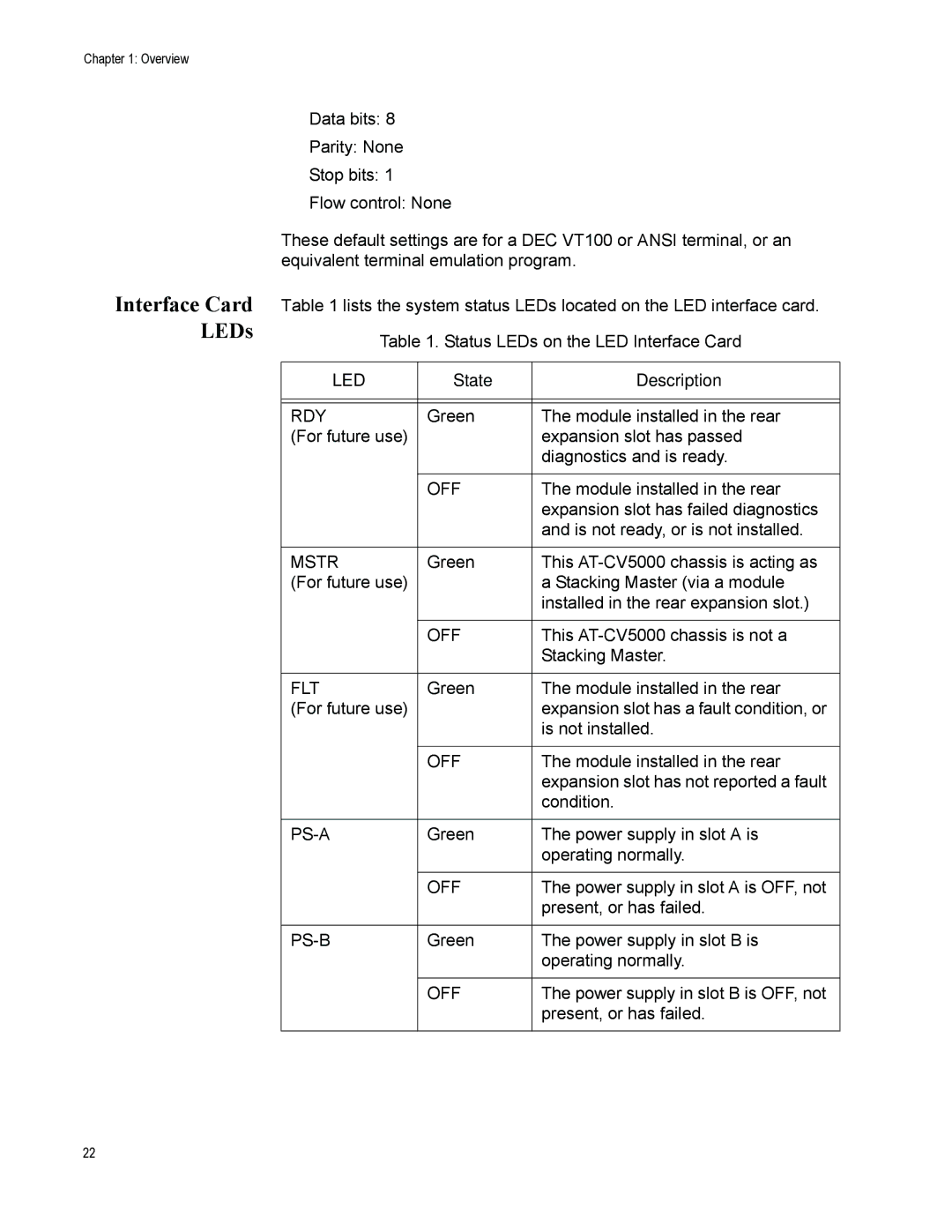
Table 1 lists the system status LEDs located on the LED interface card.
Table 1. Status LEDs on the LED Interface Card
LED | State | Description |
|
|
|
|
|
|
RDY | Green | The module installed in the rear |
(For future use) |
| expansion slot has passed |
|
| diagnostics and is ready. |
|
|
|
| OFF | The module installed in the rear |
|
| expansion slot has failed diagnostics |
|
| and is not ready, or is not installed. |
|
|
|
MSTR | Green | This |
(For future use) |
| a Stacking Master (via a module |
|
| installed in the rear expansion slot.) |
|
|
|
| OFF | This |
|
| Stacking Master. |
|
|
|
FLT | Green | The module installed in the rear |
(For future use) |
| expansion slot has a fault condition, or |
|
| is not installed. |
|
|
|
| OFF | The module installed in the rear |
|
| expansion slot has not reported a fault |
|
| condition. |
|
|
|
Green | The power supply in slot A is | |
|
| operating normally. |
|
|
|
| OFF | The power supply in slot A is OFF, not |
|
| present, or has failed. |
|
|
|
Green | The power supply in slot B is | |
|
| operating normally. |
|
|
|
| OFF | The power supply in slot B is OFF, not |
|
| present, or has failed. |
|
|
|
22