Chapter 1: Overview
AT-CV5000 Overview
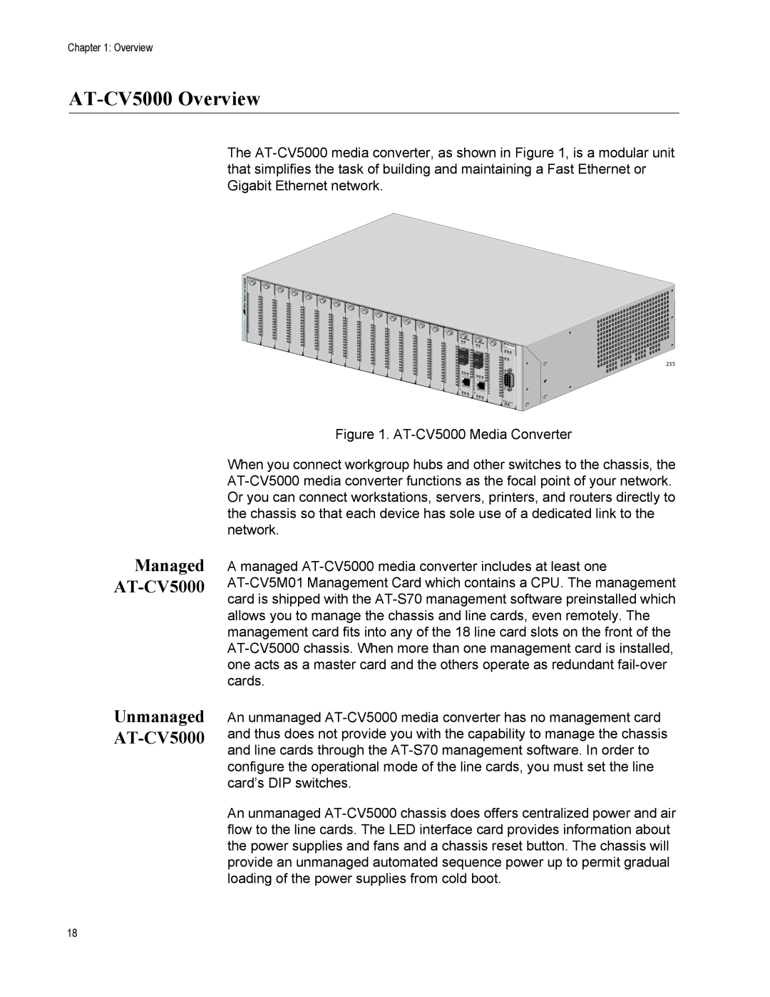
The
AT-CV5000
AT- |
|
| |
| CM202 | AT- | CM202 |
LK | AT |
| |
|
| LK | AT |
XT |
|
MM | XT |
RX | MM |
| RX |
LK | AT | FD |
|
|
|
|
| ||
|
| LK AT | FD | |
T |
|
|
| |
X |
|
|
|
|
|
| T |
|
|
|
| X |
|
|
RDY |
|
|
|
|
SML | ML | RDY |
|
|
| OAM |
|
| |
|
| SML | ML | OAM |
|
|
| ||
RDY | MSTR FLT |
FAN1 | |
PS1 |
|
REAR EXP. CONSOLE |
RESET | LINE/SFM |
235
Managed
Unmanaged
Figure 1. AT-CV5000 Media Converter
When you connect workgroup hubs and other switches to the chassis, the AT-CV5000 media converter functions as the focal point of your network. Or you can connect workstations, servers, printers, and routers directly to the chassis so that each device has sole use of a dedicated link to the network.
A managed AT-CV5000 media converter includes at least one AT-CV5M01 Management Card which contains a CPU. The management card is shipped with the AT-S70 management software preinstalled which allows you to manage the chassis and line cards, even remotely. The management card fits into any of the 18 line card slots on the front of the AT-CV5000 chassis. When more than one management card is installed, one acts as a master card and the others operate as redundant fail-over cards.
An unmanaged AT-CV5000 media converter has no management card and thus does not provide you with the capability to manage the chassis and line cards through the AT-S70 management software. In order to configure the operational mode of the line cards, you must set the line card’s DIP switches.
An unmanaged AT-CV5000 chassis does offers centralized power and air flow to the line cards. The LED interface card provides information about the power supplies and fans and a chassis reset button. The chassis will provide an unmanaged automated sequence power up to permit gradual loading of the power supplies from cold boot.
18
