AT-CV5000 Media Converter Chassis Installation Guide
Power Supplies
The
Caution
The
For information on the power supply module, refer to the documentation that is shipped with the module.
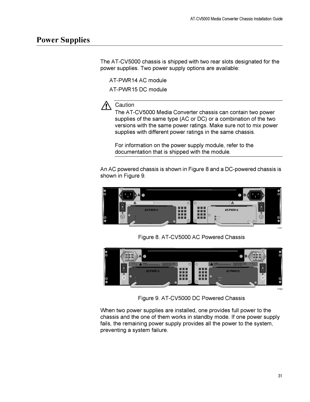
An AC powered chassis is shown in Figure 8 and a
A
![]() CVFAN-AT
CVFAN-AT
A
![]() CVFAN-AT
CVFAN-AT
|
| REAR EXP. SLOT |
|
| A | B |
|
WARNING | WARNING | ||
This unit might have more than one power input. To | This unit might have more than one power input. To | ||
reduce the risk of electric shock, disconnect all power | reduce the risk of electric shock, disconnect all power | ||
| inputs before servicing unit. | inputs before servicing unit. |
|
| |
POWER | POWER |
FAULT | FAULT |
Figure 8. AT-CV5000 AC Powered Chassis
|
|
| REAR EXP. SLOT |
|
|
| A |
|
| B |
|
| WARNING | FOR CENTRALIZED DC POWER | WARNING | FOR CENTRALIZED DC POWER |
|
This unit might have more than one power input. To | CONNECTION, INSTALL ONLY IN | This unit might have more than one power input. To | CONNECTION, INSTALL ONLY IN | ||
reduce the risk of electric shock, disconnect all power | A RESTRICTED AREA. | reduce the risk of electric shock, disconnect all power | A RESTRICTED AREA. |
POWER | POWER |
FAULT | FAULT |
Figure 9. AT-CV5000 DC Powered Chassis
B
![]()
1163
B
![]()
1162
When two power supplies are installed, one provides full power to the chassis and the one of them works in standby mode. If one power supply fails, the remaining power supply provides all the power to the system, preventing a system failure.
31