AT-CV5000 Media Converter Chassis Installation Guide
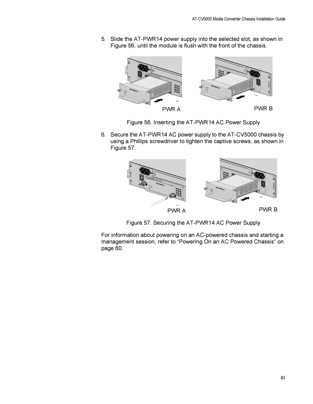
5.Slide the
A
| A |
100- |
|
240VAC~ | WARNINGThis unit |
| reduce thme ight have |
| risk of elemctorircesthhoacnko, ndeispcoownneercint paulltp.Toower |
POWER | AT- | PWR14 |
| ||
FAULT |
|
|
209
PWR A
POWER FAULT
AT-PWR14
B |
|
|
100- | 240VAC~ | B |
|
|
1129
PWR B
Figure 56. Inserting the AT-PWR14 AC Power Supply
6.Secure the AT-PWR14 AC power supply to the AT-CV5000 chassis by using a Phillips screwdriver to tighten the captive screws, as shown in Figure 57.
A ![]()
| A |
|
|
| |
|
|
|
|
| |
VAC~ | WARNINGThis |
|
|
| |
| risk | unit might | have |
|
|
| ser | of electric | than one p |
| |
|
| vicing unit. shock,mored |
| ||
|
|
| isconnect all power input |
| |
|
|
|
| ower inputs. To reduce | the |
|
|
|
| before | |
| AT- |
|
POWER | PWR1 | 4 |
FAULT |
|
|
212
PWR A
POWER FAULT
B |
|
|
100- | 240VAC~ | B |
|
|
1129
PWR B
Figure 57. Securing the AT-PWR14 AC Power Supply
For information about powering on an AC-powered chassis and starting a management session, refer to “Powering On an AC Powered Chassis” on page 60.
83