AT-CV5000 Media Converter Chassis Installation Guide
RJ-45 Twisted Pair Port Pinouts
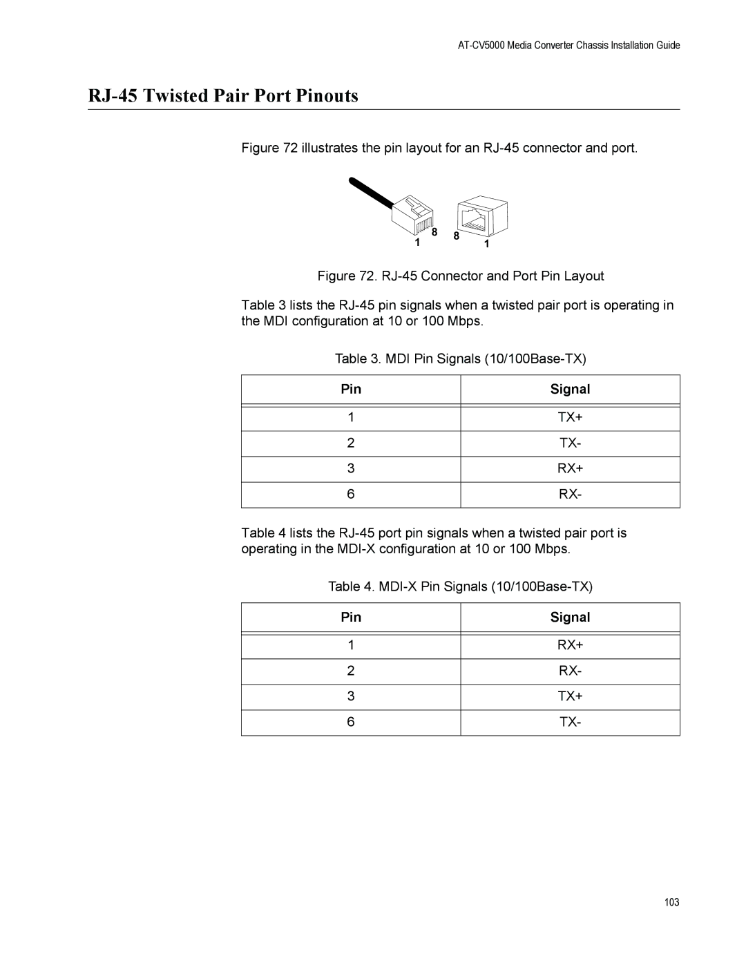
Figure 72 illustrates the pin layout for an RJ-45 connector and port.
1 | 8 | 8 |
| 1 |
Figure 72. RJ-45 Connector and Port Pin Layout
Table 3 lists the RJ-45 pin signals when a twisted pair port is operating in the MDI configuration at 10 or 100 Mbps.
Table 3. MDI Pin Signals (10/100Base-TX)
Pin | Signal |
|
|
|
|
1 | TX+ |
|
|
2 | TX- |
|
|
3 | RX+ |
|
|
6 | RX- |
|
|
Table 4 lists the
Table 4.
Pin | Signal |
|
|
|
|
1 | RX+ |
|
|
2 | RX- |
|
|
3 | TX+ |
|
|
6 | TX- |
|
|
103