Chapter 3: Working with Line Cards and other Modules
a.To install a new fan in slot A, turn the fan so that the handle is on the left and slide the new fan module into the fan slot, as shown in Figure 62.
 AT-CVFAN
A
A |
100- 240VAC~![]() tTWARNINGhheis unit mig beforriseksoerfveilecinhcttgrhicuanvseith.omck,oredtihscaonnonneecpt oalwl eprowinepruitn. pToutrseduce
tTWARNINGhheis unit mig beforriseksoerfveilecinhcttgrhicuanvseith.omck,oredtihscaonnonneecpt oalwl eprowinepruitn. pToutrseduce
| AT- |
POWER | PWR14 |
FAULT |
|
202
-
Figure 62. Inserting an AT-CVFAN Module into Fan Slot A
b.To install a new fan in slot B, turn the fan so that the handle is on the right and slide the new fan module into the fan slot, as shown in Figure 63, until the front of the fan module is flush with the front of the chassis.
A ![]() TCV5FAN-
TCV5FAN-
| A | |
VAC~ | ||
|
| |
|
| AT |
| POWE | R |
|
| |
| FAULT |
|
B |
|
VAC~ | |
|
4 AT-PWR1
POWE | R |
FAULT |
|
B
![]()
203
Figure 63. Inserting an AT-CVFAN Module into Fan Slot B
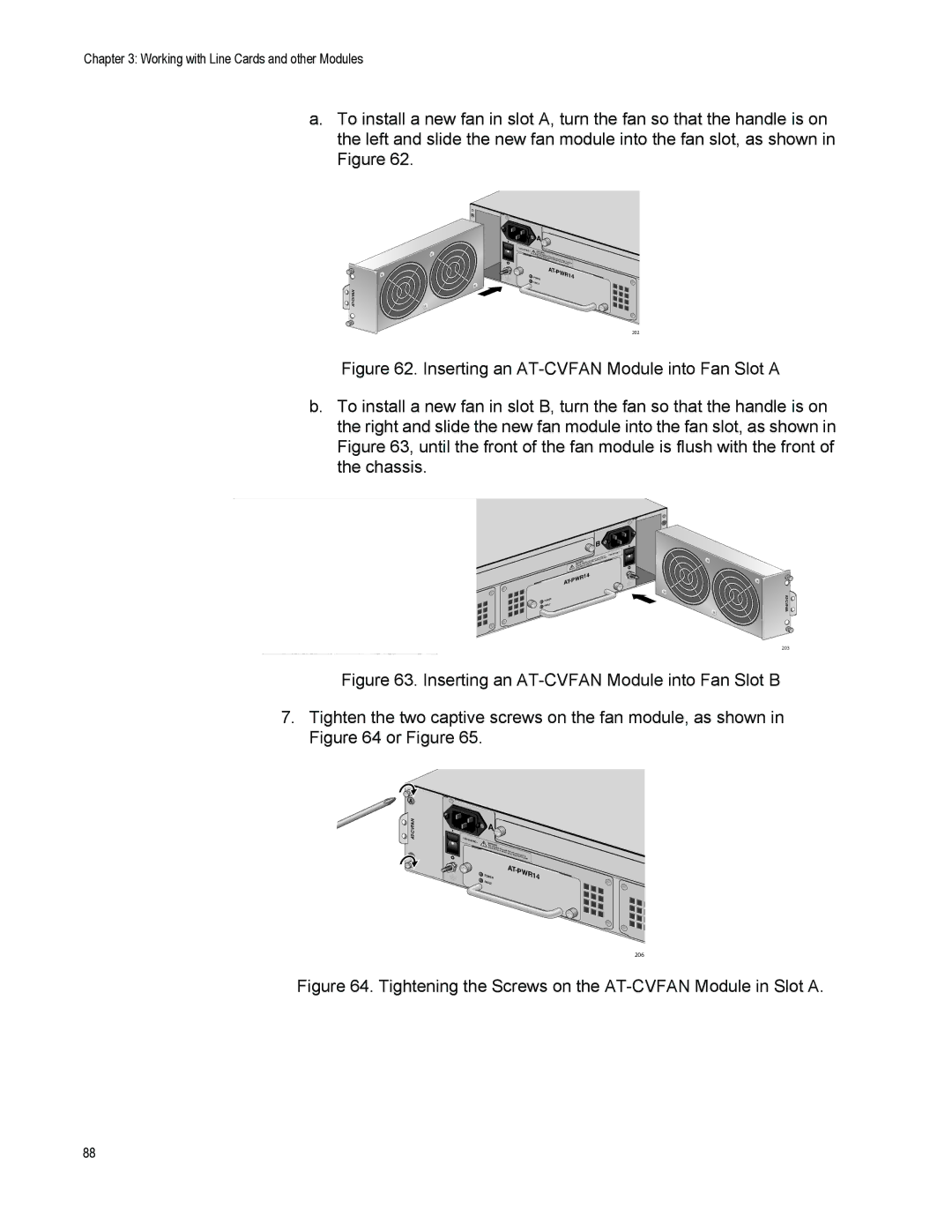
7.Tighten the two captive screws on the fan module, as shown in Figure 64 or Figure 65.
 A
A 
CVFAN-AT
| A |
|
|
|
|
100- |
|
|
|
|
|
240VAC~ | WARNING |
|
|
| |
|
|
|
| ||
| This unit | might |
|
|
|
| reduce |
|
|
| |
|
| the risk have | more than |
| |
|
| of |
|
| |
|
|
| electric shock,one power |
| |
|
|
|
| disconnectinput. To |
|
|
|
|
| all power |
|
|
|
|
| AT- |
|
| POWER |
|
| PW | R14 |
| FAULT |
|
|
|
|
206
Figure 64. Tightening the Screws on the AT-CVFAN Module in Slot A.
88