Chapter 2: Installation
Installing the Power Cord Retaining Clip (AC Powered Chassis Only)
To install the power cord retaining clip on an
1. Locate the power cord retaining clip which is shown in Figure 14.
Figure 14. Power Cord Retaining Clip
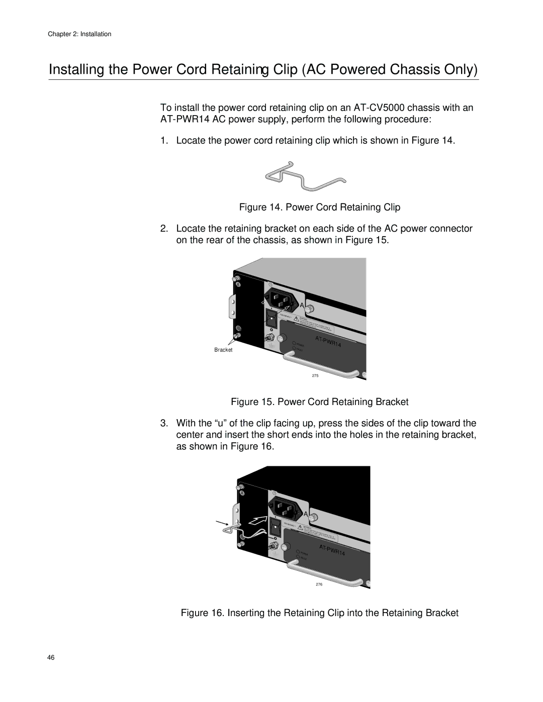
2.Locate the retaining bracket on each side of the AC power connector on the rear of the chassis, as shown in Figure 15.
A
Bracket
| A |
|
|
|
|
|
|
|
|
|
| ||
100- |
|
|
|
|
|
|
|
|
|
|
|
|
|
240VAC~ | WARNINGThis u |
|
|
|
|
|
|
|
|
|
| ||
|
|
|
|
|
|
|
|
|
|
| |||
| red |
| nit |
| have |
|
|
|
|
|
|
| |
|
| uce thmighte | more |
|
|
|
|
| |||||
| inputs | risk of |
| than o |
|
|
|
| |||||
|
|
| before |
|
| elect |
|
|
|
|
| ||
|
|
|
| servicingric shock, ne power | input. |
| |||||||
|
|
|
|
|
|
|
| unit. | disco |
| To | ||
|
|
|
|
|
|
|
|
|
|
| nnect all | ||
|
|
|
|
|
|
|
|
|
|
|
| power | |
| WER |
|
|
|
|
| AT- | PWR14 | |||||
| PO |
|
|
|
|
|
|
|
|
|
|
|
|
| F |
|
|
|
|
|
|
|
|
|
|
|
|
| AULT |
|
|
|
|
|
|
|
|
|
|
| |
275
Figure 15. Power Cord Retaining Bracket
3.With the “u” of the clip facing up, press the sides of the clip toward the center and insert the short ends into the holes in the retaining bracket, as shown in Figure 16.
A
| A |
|
|
|
|
100- |
|
|
|
|
|
240VAC~ | WARNINGhis un |
|
|
|
|
| T |
|
|
|
|
| inrepduutsce itthme rigishkt have mo | re than |
|
| |
| before | of elec |
|
| |
|
| servicingtruicnsith. ocko, ndeispcoower input. | To | ||
|
|
| nnect all | ||
|
|
|
|
| power |
| WER |
| AT- | PWR14 | |
| PO |
|
|
|
|
| F |
|
|
|
|
| AULT |
|
|
|
|
276
Figure 16. Inserting the Retaining Clip into the Retaining Bracket
46