AT-CV5000 Media Converter Chassis Installation Guide
B |
|
|
0VAC | ~ | |
|
| |
TWAhisRNINGunthit me rigishkt ohfaveelemctroicresthhoacnko, ndeispcoownneercint paulltp. Toower |
|
|
reduce |
|
|
|
| |
AT |
|
|
B ![]()
![]() A
A ![]()
POWE | R |
T |
|
FAUL |
|
A ![]() 5FAN
5FAN
VAC~ | |
|
AT-CV5PWRAC
R
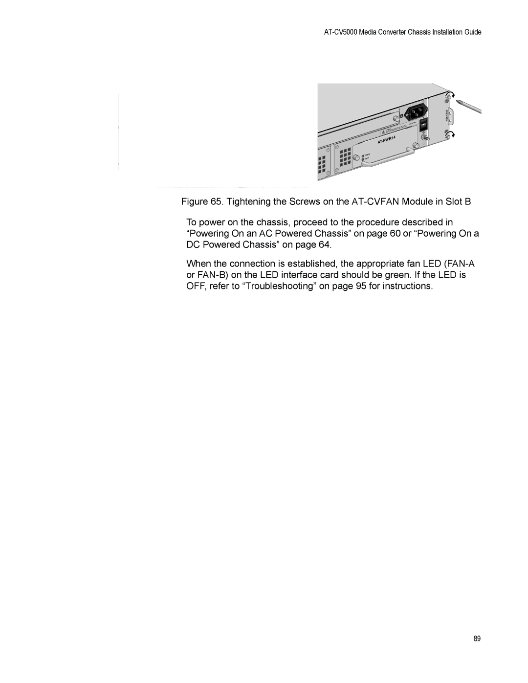
Figure 65. Tightening the Screws on the AT-CVFAN Module in Slot B
To power on the chassis, proceed to the procedure described in “Powering On an AC Powered Chassis” on page 60 or “Powering On a DC Powered Chassis” on page 64.
When the connection is established, the appropriate fan LED (FAN-A or FAN-B) on the LED interface card should be green. If the LED is OFF, refer to “Troubleshooting” on page 95 for instructions.
89