6.Repeat steps 3 through 5 to set the other date/time fields, as needed.
7.Do one of the following:
−To save the new date/time settings and then exit, return the keyboard to Operate mode.
−To exit without saving the new settings, press Clear, and return the keyboard to Operate mode. The monitor displays the original date/time settings.
Setting Port Configurations
Each MegaPower CPU provides the following port types:
•Keyboard
•Recorder
•Satellite
•Alarms
•Alarms
•Alarms
•Alarms
•Terminal
•Auxiliary
•Video Loss Detection
•Video Loss Detection
•Video Loss Detection
•Video Loss Detection
The Port Configuration setup allows you to identify the device type (keyboard, port expansion module, and others), baud rate, and other communications parameters of each device connected to a port on the CPU.
Important: The MegaPower CPU can support up to 128 keyboards using port expansion modules. Port expansion modules convert a single port into four ports. When a port expansion module is connected to a port, port numbering adds an alpha character (a, b, c, d) to each port number; for example, port one becomes ports 1a, 1b, 1c, 1d; port two becomes ports 2a, 2b, 2c, 2d, and so on.
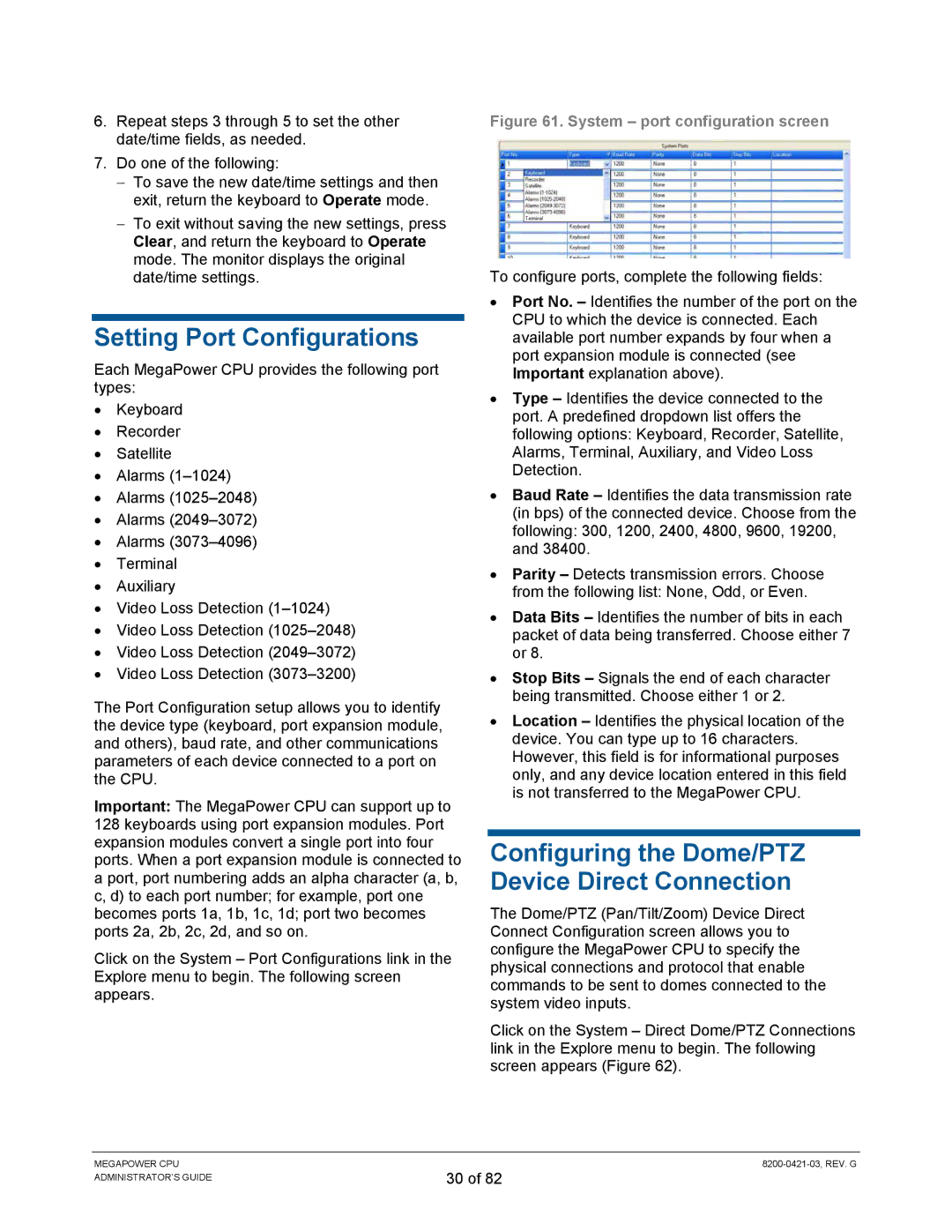
Click on the System – Port Configurations link in the Explore menu to begin. The following screen appears.
Figure 61. System – port configuration screen
To configure ports, complete the following fields:
•Port No. – Identifies the number of the port on the CPU to which the device is connected. Each available port number expands by four when a port expansion module is connected (see Important explanation above).
•Type – Identifies the device connected to the port. A predefined dropdown list offers the following options: Keyboard, Recorder, Satellite, Alarms, Terminal, Auxiliary, and Video Loss Detection.
•Baud Rate – Identifies the data transmission rate (in bps) of the connected device. Choose from the following: 300, 1200, 2400, 4800, 9600, 19200, and 38400.
•Parity – Detects transmission errors. Choose from the following list: None, Odd, or Even.
•Data Bits – Identifies the number of bits in each packet of data being transferred. Choose either 7 or 8.
•Stop Bits – Signals the end of each character being transmitted. Choose either 1 or 2.
•Location – Identifies the physical location of the device. You can type up to 16 characters. However, this field is for informational purposes only, and any device location entered in this field is not transferred to the MegaPower CPU.
Configuring the Dome/PTZ Device Direct Connection
The Dome/PTZ (Pan/Tilt/Zoom) Device Direct Connect Configuration screen allows you to configure the MegaPower CPU to specify the physical connections and protocol that enable commands to be sent to domes connected to the system video inputs.
Click on the System – Direct Dome/PTZ Connections link in the Explore menu to begin. The following screen appears (Figure 62).
MEGAPOWER CPU ADMINISTRATOR’S GUIDE
30 of 82