Table 1 describes the valid setting values that can be specified for the four port groups:
Table 1. Valid Port Group settings
| Direct Connect |
|
| SensorNet/ |
|
|
| |
|
|
| Manchester |
|
|
| ||
| Settings Description |
|
|
|
|
| ||
|
|
| 1/2 |
|
| 1/2 |
| |
|
|
|
|
|
|
| ||
| Dome/PTZ Control: |
| SensorNet |
| ||||
| Specifies the port |
| or |
| or | |||
| protocol |
| Manchester |
| ||||
|
|
|
|
|
| |||
| Patterns (SensorNet/ |
| Variable |
| Variable | |||
| Manchester) or |
| or |
| or | |||
| Default Mode |
| Legacy |
| Legacy | |||
|
|
|
|
|
|
| ||
| Specifies whether to |
|
|
|
|
|
| |
| use variable or legacy |
|
|
|
|
|
| |
| speed patterns |
|
|
|
|
|
| |
| Starting Video Input |
| 1 to 3200 |
| 1 to 3200 | |||
| Number: Physical |
|
|
|
|
|
| |
| video connection |
|
|
|
|
|
| |
| number that defines |
|
|
|
|
|
| |
| start of group of inputs |
|
|
|
|
|
| |
| controlled on this port |
|
|
|
|
|
| |
|
|
|
|
|
| |||
| Starting Dome/PTZ |
| 1 to 254 |
| 1 to 100 | |||
| Address: The address |
| (SensorNet) |
|
|
| ||
| setting of the first |
| or |
|
|
| ||
| (lowest address) |
| 1 to 64 |
|
|
| ||
| Dome/PTZ connected |
| (Manchester) |
|
|
| ||
| to video inputs on this |
|
|
|
|
|
| |
| port |
|
|
|
|
|
| |
|
|
|
|
|
| |||
| No. of Dome/PTZ |
| 0 to 254* |
| 0 to 100* | |||
| Devices: The number |
| (SensorNet) |
| *See note. | |||
| of Dome/PTZ devices |
| or |
|
|
| ||
| connected to this port. |
| 0 to 64* |
|
|
| ||
|
|
|
| (Manchester) |
|
|
| |
|
|
|
| *See note. |
|
|
| |
|
|
|
|
|
|
|
|
|
Note: The maximum value actually allowed for this setting is the lesser of:
•The nominal maximum value: 254, 64, or 100 or
•Maximum video inputs (3200) minus Starting Video Input No. + 1
Configuring Switching
Switching provides many of the automated functions designed to enhance your video surveillance practices. It allows you to create Salvos and set up Tours that will run automatically. You can also use switching to schedule different alarm monitor/contact tables to become active at different times and days.
Click on the Switching links in the Explore menu to begin (Figure 63 on page 32).
Figure 63. Switching links
Creating Salvos
A system Salvo is a group of cameras programmed to display simultaneously on a contiguous group of monitors. The MegaPower CPU allows you to create up to 200 Salvos.
You can place up to 16 cameras in each Salvo, with each camera having its own dwell time, Preset view, auxiliary action, and link status. You can also insert a Salvo as the last entry of a Salvo (in place of a camera). This “nesting” of a Salvo within a Salvo expands the number of different camera views.
Click on the Switching – Salvo link in the Explore menu to begin. The following screen appears.
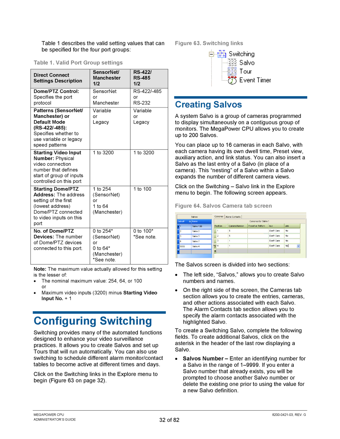
Figure 64. Salvos Camera tab screen
The Salvos screen is divided into two sections:
•The left side, “Salvos,” allows you to create Salvo numbers and names.
•On the right side of the screen, the Cameras tab section allows you to create the entries, cameras, and other actions associated with each Salvo.
The Alarm Contacts tab section allows you to specify the alarm contacts associated with the highlighted Salvo.
To create a Switching Salvo, complete the following fields. To create additional Salvos, click on the asterisk in the header of the last row displaying a Salvo.
•Salvos Number – Enter an identifying number for a Salvo in the range of
MEGAPOWER CPU ADMINISTRATOR’S GUIDE
32 of 82