Figure 80. Delete Rows dialog | • Preset or Pattern – Indicates a Preset |
| Pattern number |
| number or Salvo selected above. Enter the |
| number of a Preset or Pattern for the |
| corresponding camera number or Salvo field as |
| follows: |
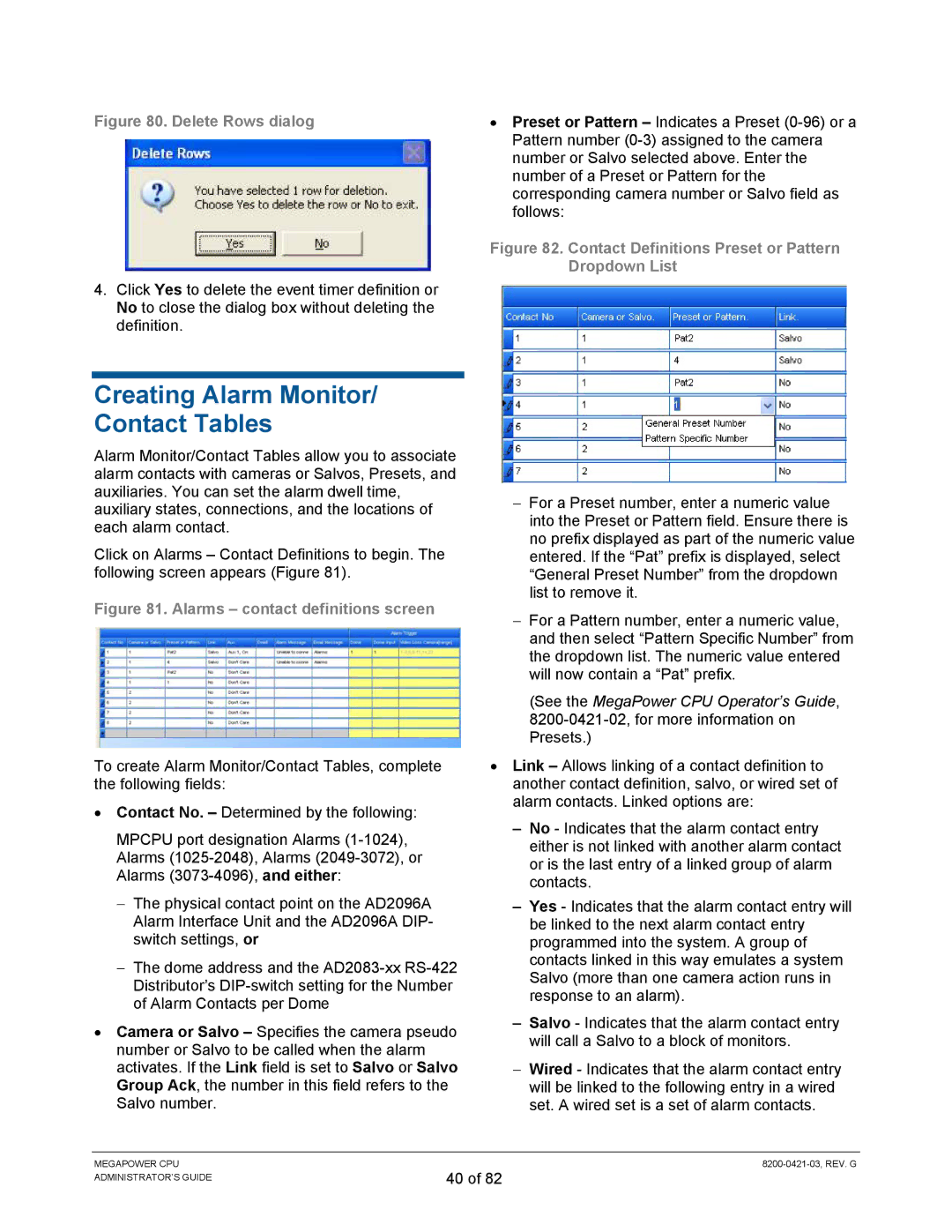
| Figure 82. Contact Definitions Preset or Pattern |
| Dropdown List |
4.Click Yes to delete the event timer definition or No to close the dialog box without deleting the definition.
Creating Alarm Monitor/ Contact Tables
Alarm Monitor/Contact Tables allow you to associate alarm contacts with cameras or Salvos, Presets, and auxiliaries. You can set the alarm dwell time, auxiliary states, connections, and the locations of each alarm contact.
Click on Alarms – Contact Definitions to begin. The following screen appears (Figure 81).
Figure 81. Alarms – contact definitions screen
To create Alarm Monitor/Contact Tables, complete the following fields:
•Contact No. – Determined by the following:
MPCPU port designation Alarms
−The physical contact point on the AD2096A Alarm Interface Unit and the AD2096A DIP- switch settings, or
−The dome address and the
•Camera or Salvo – Specifies the camera pseudo number or Salvo to be called when the alarm activates. If the Link field is set to Salvo or Salvo Group Ack, the number in this field refers to the Salvo number.
−For a Preset number, enter a numeric value into the Preset or Pattern field. Ensure there is no prefix displayed as part of the numeric value entered. If the “Pat” prefix is displayed, select “General Preset Number” from the dropdown list to remove it.
−For a Pattern number, enter a numeric value, and then select “Pattern Specific Number” from the dropdown list. The numeric value entered will now contain a “Pat” prefix.
(See the MegaPower CPU Operator’s Guide,
•Link – Allows linking of a contact definition to another contact definition, salvo, or wired set of alarm contacts. Linked options are:
– No - Indicates that the alarm contact entry either is not linked with another alarm contact or is the last entry of a linked group of alarm contacts.
– Yes - Indicates that the alarm contact entry will be linked to the next alarm contact entry programmed into the system. A group of contacts linked in this way emulates a system Salvo (more than one camera action runs in response to an alarm).
– Salvo - Indicates that the alarm contact entry will call a Salvo to a block of monitors.
−Wired - Indicates that the alarm contact entry will be linked to the following entry in a wired set. A wired set is a set of alarm contacts.
MEGAPOWER CPU ADMINISTRATOR’S GUIDE
40 of 82