American Power Conversion InfraStruXureTM System manual Cross Tie Output Circuit Breaker, Overview

Models: InfraStruXureTM System

1 100
Download 100 pages 51.56 Kb
Page 22
Image 22

Cross Tie Output Circuit Breaker

Overview

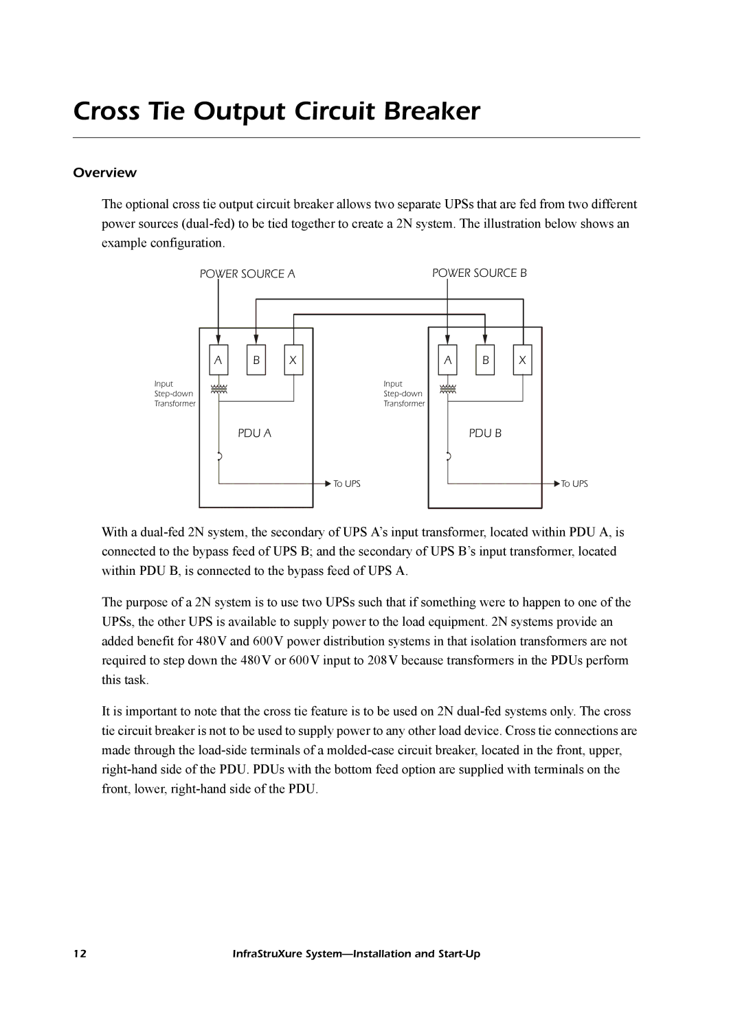
The optional cross tie output circuit breaker allows two separate UPSs that are fed from two different power sources (dual-fed) to be tied together to create a 2N system. The illustration below shows an example configuration.

POWER SOURCE A

POWER SOURCE B

A

Input

Step-down

Transformer

B

PDU A

X

A

Input

Step-down

Transformer

To UPS

B

PDU B

X

To UPS

With a dual-fed 2N system, the secondary of UPS A’s input transformer, located within PDU A, is connected to the bypass feed of UPS B; and the secondary of UPS B’s input transformer, located within PDU B, is connected to the bypass feed of UPS A.

The purpose of a 2N system is to use two UPSs such that if something were to happen to one of the UPSs, the other UPS is available to supply power to the load equipment. 2N systems provide an added benefit for 480V and 600V power distribution systems in that isolation transformers are not required to step down the 480V or 600V input to 208V because transformers in the PDUs perform this task.

It is important to note that the cross tie feature is to be used on 2N dual-fed systems only. The cross tie circuit breaker is not to be used to supply power to any other load device. Cross tie connections are made through the load-side terminals of a molded-case circuit breaker, located in the front, upper, right-hand side of the PDU. PDUs with the bottom feed option are supplied with terminals on the front, lower, right-hand side of the PDU.

12

InfraStruXure System—Installation and Start-Up

Page 22
Image 22
American Power Conversion InfraStruXureTM System manual Cross Tie Output Circuit Breaker, Overview