Installation Procedures: Connect AC Power and Control Wiring
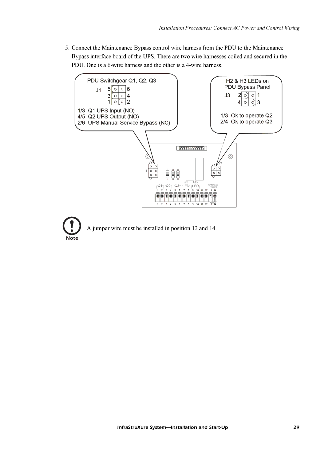
5.Connect the Maintenance Bypass control wire harness from the PDU to the Maintenance Bypass interface board of the UPS. There are two wire harnesses coiled and secured in the PDU. One is a
PDU Switchgear Q1, Q2, Q3
J1 | 5 | 6 |
34
1 2
1/3 Q1 UPS Input (NO)
4/5 Q2 UPS Output (NO)
2/6 UPS Manual Service Bypass (NC)
H2 & H3 LEDs on PDU Bypass Panel
J3 | 2 | 1 |
43
1/3 Ok to operate Q2 2/4 Ok to operate Q3
J1 |
|
|
|
|
|
|
|
|
|
|
|
|
|
Q1 | Q2 | Q3 | Q2 | Q3 |
|
| Switchgear | ||||||
LED | LED |
|
| ||||||||||
|
| Present | |||||||||||
1 | 2 | 3 | 4 | 5 | 6 | 7 | 8 | 9 | 10 | 11 | 12 | 13 | 14 |
1 | 2 | 3 | 4 | 5 | 6 | 7 | 8 | 9 | 10 | 11 | 12 | 13 | 14 |
A jumper wire must be installed in position 13 and 14.
Note
InfraStruXure | 29 |