Installation Procedures: Connect AC Power and Control Wiring
Connect control wiring.
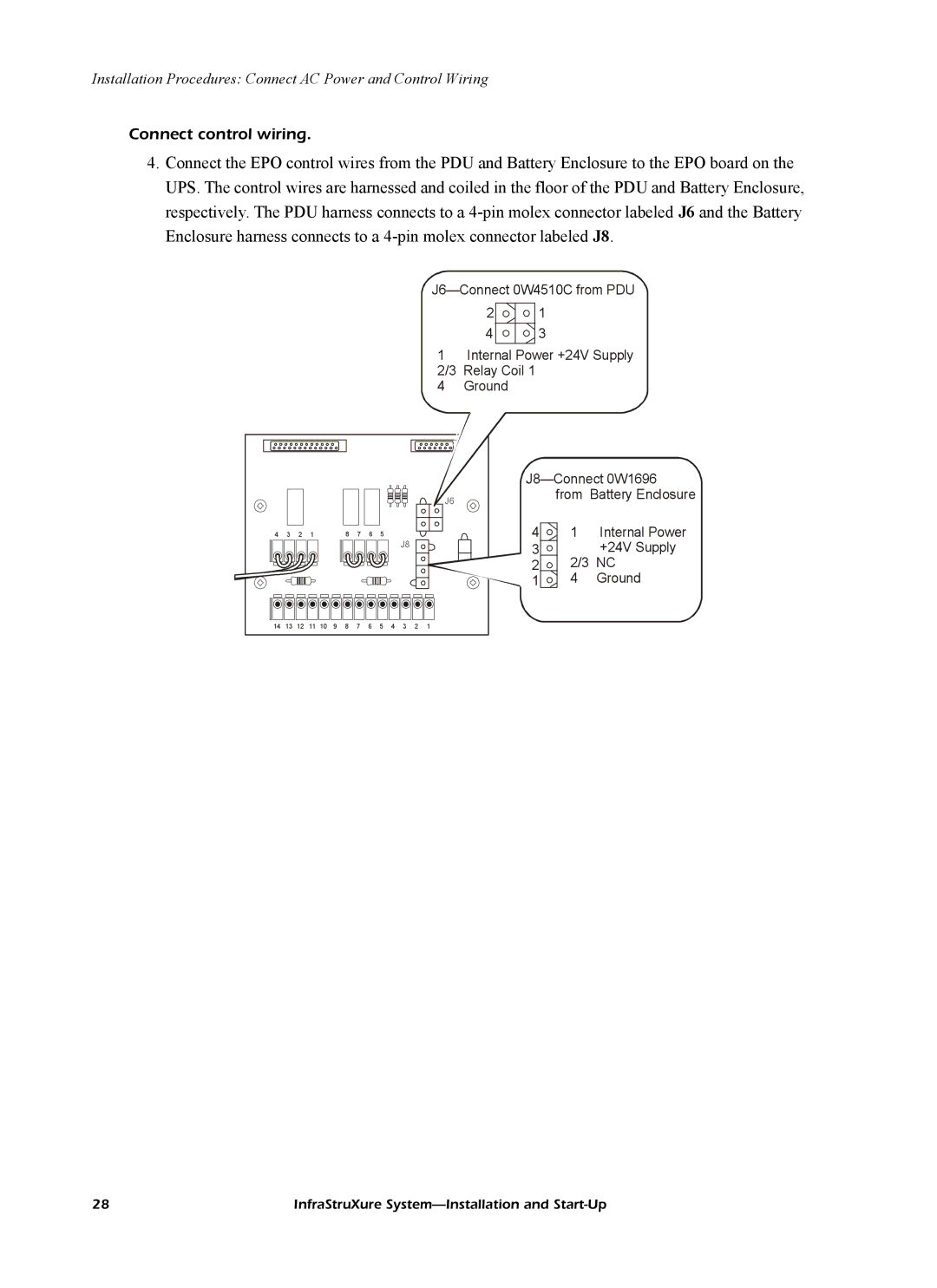
4.Connect the EPO control wires from the PDU and Battery Enclosure to the EPO board on the UPS. The control wires are harnessed and coiled in the floor of the PDU and Battery Enclosure, respectively. The PDU harness connects to a
2 1
4 3
1Internal Power +24V Supply 2/3 Relay Coil 1
4 Ground
|
|
|
|
|
|
|
|
|
|
|
|
| |||
|
|
|
|
|
|
|
|
|
|
|
|
| J6 | from | Battery Enclosure |
|
|
|
|
|
|
|
|
|
|
|
|
|
|
| |
4 | 3 | 2 | 1 |
|
| 8 | 7 | 6 | 5 |
|
|
| 4 | 1 | Internal Power |
|
|
|
|
|
|
|
|
|
|
| J8 |
| 3 |
| +24V Supply |
|
|
|
|
|
|
|
|
|
|
|
|
|
| ||
|
|
|
|
|
|
|
|
|
|
|
|
| 2 | 2/3 NC | |
|
|
|
|
|
|
|
|
|
|
|
|
| 1 | 4 | Ground |
14 | 13 | 12 | 11 | 10 | 9 | 8 | 7 | 6 | 5 | 4 | 3 | 2 | 1 |
|
|
28 | InfraStruXure |