Connect User Input Contacts and Relay Outputs to the User Connection Plate
Overview
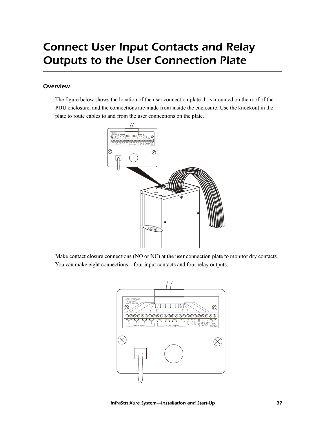
The figure below shows the location of the user connection plate. It is mounted on the roof of the PDU enclosure, and the connections are made from inside the enclosure. Use the knockout in the plate to route cables to and from the user connections on the plate.
USER INTERFACE
© 2001 APC MADE IN USA
1 | 2 | 3 | 4 |
|
| Contact Outputs |
| |
| Contact Inputs |
|
|
|
| |||
|
|
|
|
|
|
|
|
|
|
|
|
|
|
|
|
|
|
ATS 0 ATS 1 ATS 2
ATSEN
–+ ![]() EPO 24V EPO AC/DC Contact
EPO 24V EPO AC/DC Contact
Make contact closure connections (NO or NC) at the user connection plate to monitor dry contacts. You can make eight
USER INTERFACE
©2001 APC MADE IN USA
1 | 2 | 3 |
| 4 | |
| Contact Inputs |
|
| ||
|
|
|
|
|
|
|
|
|
|
|
|
![]()
![]() Contact Outputs
Contact Outputs![]()
![]()
ATS 0 ATS 1 ATS 2
ATS EN
–+ ![]() EPO 24V EPO AC/DC Contact
EPO 24V EPO AC/DC Contact
InfraStruXure | 37 |