Configuring Communications
Step 3: Choose a Master Connection Mode
The panel requires you establish the type of connection you want made between it and your master.
In the Protected Setup page:
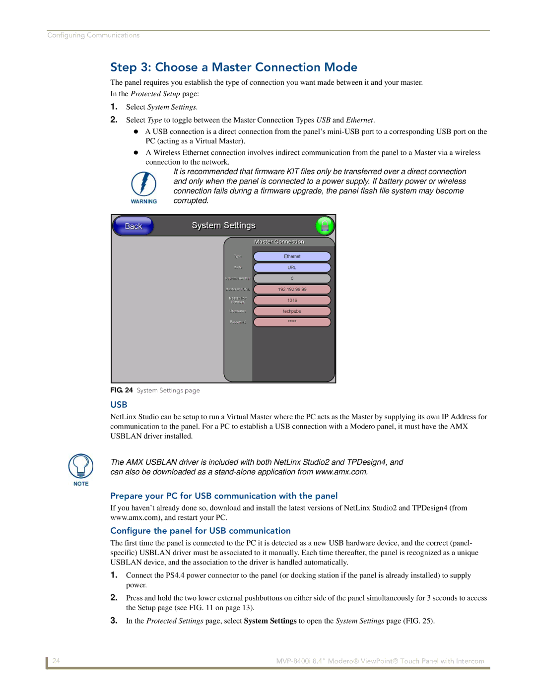
1.Select System Settings.
2.Select Type to toggle between the Master Connection Types USB and Ethernet.
A USB connection is a direct connection from the panel’s
A Wireless Ethernet connection involves indirect communication from the panel to a Master via a wireless connection to the network.
It is recommended that firmware KIT files only be transferred over a direct connection and only when the panel is connected to a power supply. If battery power or wireless connection fails during a firmware upgrade, the panel flash file system may become corrupted.
FIG. 24 System Settings page
USB
NetLinx Studio can be setup to run a Virtual Master where the PC acts as the Master by supplying its own IP Address for communication to the panel. For a PC to establish a USB connection with a Modero panel, it must have the AMX USBLAN driver installed.
The AMX USBLAN driver is included with both NetLinx Studio2 and TPDesign4, and can also be downloaded as a
Prepare your PC for USB communication with the panel
If you haven’t already done so, download and install the latest versions of NetLinx Studio2 and TPDesign4 (from www.amx.com), and restart your PC.
Configure the panel for USB communication
The first time the panel is connected to the PC it is detected as a new USB hardware device, and the correct (panel- specific) USBLAN driver must be associated to it manually. Each time thereafter, the panel is recognized as a unique USBLAN device, and the association to the driver is handled automatically.
1.Connect the PS4.4 power connector to the panel (or docking station if the panel is already installed) to supply power.
2.Press and hold the two lower external pushbuttons on either side of the panel simultaneously for 3 seconds to access the Setup page (see FIG. 11 on page 13).
3.In the Protected Settings page, select System Settings to open the System Settings page (FIG. 25).
24 |
