Modero NXD-500i
AMX Limited Warranty and Disclaimer
Table of Contents
Upgrading Modero Firmware
Programming
Page
Introduction
Ethernet 10/100 port Mini-USB port Back box
NXD-500i Specifications
Specifications for the 5 Widescreen Modero panel include
Button Assignments
Specifications for NCXC-500i 5 Widescreen Video Touch Panel
Side Panel Components
Operating / Storage
Ethernet and mini-USB Ports
Included Accessories
Front Bezel Button
Other AMX Equipment
Page
Installation
Installing the Trim Ring
Removing the Faceplate
Installation of an NXD-500i Touch Panel
Pre-Wall Installation of the Rough-In Box
Installing the NXD-500i panel within a Rough-In Box
Installation
Installing the NXD-500i into drywall
NXD-500i backbox with closed and open locking tabs
NXD-500i Wall Mount panel dimensions
Installation
Installing the NXD-500i into a Flat Surface using #4 screws
Flat installation surface
Installing an NXD-500i into a Rack Mount Kit NXA-RK5
Ethernet RJ-45 Pinouts and Signals
Wiring Guidelines for the NXD-500i Panel
Ethernet/RJ-45 Port Connections and Wiring
Pin Signals Connections Pairing Color
Input Specifications
PS-POE-AF Specifications
Output Specifications
PS-POE-AF PoE Injector
EMC Information
General Specifications
Environmental Specifications
Panel Calibration
Calibrating the Modero Panel
Panel Calibration
Configuring Communication
Modero Setup and System Connection
Modero connection information
Confirm the Installation of the USB Driver on the PC
Configuring and Using USB with a Virtual Master
Setup the Panel and PC for USB Communication
To setting up a USB connection to the panel
Confirm and View the current AMX USB device connections
Device Manager dialog showing USB device
USB
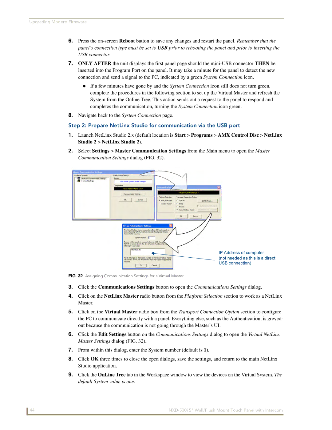
Assigning Communication Settings for a Virtual Master
Repopulating the System List
Configuring a Wired Ethernet Connection
Configure the Panel’s Wired IP Settings
Choose a Master Connection Mode Setting
Configure an Ethernet Connection Type
Obtained From NetLinx Master
Configuring Communication
These must match
Resides on the same Subnet as itself
Using G4 Web Control to Interact with a G4 Panel
G4 Web Control
Using the NetLinx Master to control the G4 panel
G4 panels
Wireless Not available with the NXD-500i panel
If this field does not appear, continue to step
Configuring Communication
Page
Configure the panel for a USB Connection Type
Upgrading the Firmware via the USB port
Prepare NetLinx Studio for communication via the USB port
Confirm and Upgrade the firmware via the USB port
Default Modero panel value is
Using USB for a Virtual Master transfer
Setup Navigation Buttons
Protected Setup
Setup Page Elements
Setup
Elements of the Setup page are described below
Panel Brightness
Inactivity Page Flip
Time
Project Information Page Elements
Information
Panel Information
Elements of the Panel Information page are as follows
Panel Information Page Elements
Screen Rotation
Power Up Pages
Screen Refresh Rate
Start Up String
Time & Date Setup Page Elements
Time & Date Settings
Elements of the Time & Date Setup page are as follows
Time & Date Settings Page Elements
Audio Settings
Elements of the Audio Settings page are as follows
Audio Settings Page Elements
Supported WAV Sampling Rates
Volume Page Elements
Supported sampling rates for WAV
Protected Setup Navigation Buttons
Passwords
Options
Protected Setup Page Elements
Device ID
Button
System Recovery
Reboot/Shutdown Panel
Slider
System Settings Page Elements
System Settings
Elements of the System Settings page are as follows
IP Settings
Full Duplex
USB IP Settings
System Connection Page Elements
Master Connection
Calibration
Calibration page actually 3 separate screens
G4 Web Control Page Elements
G4 Web Control Settings
G4 Web Control
G4 Web Control Timeout
Cache Settings Page Elements
Other Settings
Cache Settings
Image Cache Settings
Clear Cache
Setting the image cache
Enable
Image Cache Status
Clearing the image cache
Checking image cache status
Password Settings
Password Settings
Features on this page include
Panel Password
Light
Sensor Setup
Sensor Setup Page Elements
Light Sensor
Motion
Making the most of the Motion Sensor feature
Making the most of the Light bargraph
Tools
Tools menu
Checking the Panel Connection Logs
Features on this page are as follows
Panel Logs
Refreshing the Panel Connections Log
Panel Statistics
Clearing the Panel Connections Log
Panel Statistics
Clearing the Panel Statistics
Checking the Panel Statistics
Refreshing the Panel Statistics
Connection Utility
Connection Utility
Using the Connection Utility
Page
Button Assignments
Commands
Commands
@APG
@PHE
@DPG
@PDR
@PHP
Commands
@PPT
@PPM
@PPN
@PPX
@PST
@PSE
@PSP
Ppon
Ppof
Ppog
RGB Values for all 88 Basic Colors
Programming Numbers for Colors, Fonts, and Borders
RGB triplets and names for basic 88 colors
Index No Name Red Green Blue
RGB Values for all 88 Basic Colors
Font ID # Font type Size
Default Font Styles and ID Numbers
Font styles and ID numbers
TPD4 Border Styles by Name
Border styles and Programming numbers
Border Styles and Programming Numbers
Border styles
TPD4 Border Styles by Name
Telnet Commands
Telnet Commands
ANI
Button Commands
Button Commands
APF
BCF
BAU
BCB
BFB
BCT
BDO
BLN
BIM
Entry is required
Sendcommand Panel,BMC-150,1,1,315,1,%BR%FT%TX%BM%IC%CF%CT
BMC
BMF
BMF-vt addr range,button states range,data
Cont
BMP
BMI
BML
BNC
BOR
BNT
BOP
BRD
BOS
BPP
BSF
BVL
BSM
BSO
BVN
CPF
BVT
BWW
DPF
GDI
ENA
FON
GLL
GIV
GLH
GRD
ICO
GSC
GSN
JSB
JSI
Pass data
JST
MBT
MDC
Effect names
TEC
TEF
TXT
UNI
Sendcommand Panel,UNI-500,1,0041
Sendcommand TP,UNI-1,0,0041
UNI-vt addr range,button states range,unicode text
Text Effect Names
Text Effects
Button Query Commands
Defineevent
Custom Event Fields
Button Query Commands
All custom events have the following 6 fields
Field Description
?BCF
?BCT
?BMP
?BOP
?BRD
?BWW
?FON
?ICO
?JSB
?JSI
?JST
?TEC
?TEF
Send Command Panel,?TEF-529,1
Send Command Panel,?TXT-529,1
?TEF-vt addr range,button states range
Panel Runtime Operation Commands
Panel Runtime Operations
Beep
@AKP
@AKR
Brit
Pkeyp
Setup
@EKP
@PKP
Tpageon
@SOU
@TKP
Tpageoff
Input Commands
Input Commands
These Send Commands are case insensitive
Embedded Codes
Embedded codes
Following is a list of G4-compatible embedded codes
Decimal numbers Hexidecimal values Virtual keystroke
Panel Setup Commands
Panel Setup Commands
These commands are case insensitive
Dynamic Image Commands
Dynamic Image Commands
RAF-resource name,data
Intercom Commands
Intercom Commands
Following is a list of Intercom Commands
ICM-LISTEN
ICE
ICM-TALK
IRM
Panel IR Commands
Panel IR Commands
IRS
Page
Troubleshooting Information
Connecting
Symptom Solution My Modero panel can’t obtain a
Settings Stop Communications
Dhcp Address
Crawling, dashed line
Symptom Solution Panel doesn’t respond to my
Touches
My connected Masters
Symptom Solution After downloading a panel file or
Behaves strangely
Bargraph Text Code Inputs
Following is a code list used for bargraphs
Text Formatting Codes for Bargraphs/Joysticks
Formatting Code Operations
Input mask character types
With this feature, it is not necessary to
Text Area Input Masking
Character Types
Input mask operations
Input mask ranges
Input mask next field characters
Input mask literals
Output Examples
Input mask output examples
Following are some common input masking examples
Common Name Input Mask
Escape Sequences
URL Resources
Special escape sequences
Sequence Panel Information
Page
Page
It’s Your World Take Control