ADuC812
I2C-COMPATIBLE INTERFACE
The ADuC812 supports a
SDATA (Pin 27) | Serial data I/O Pin |
SCLOCK (Pin 26) | Serial Clock |
previously). An Application Note describing the operation of this interface as implemented is available from the MicroConverter Website at www.analog.com/microconverter. This interface can be configured as a Software Master or Hardware Slave, and uses two pins in the interface.
Three SFRs are used to control the
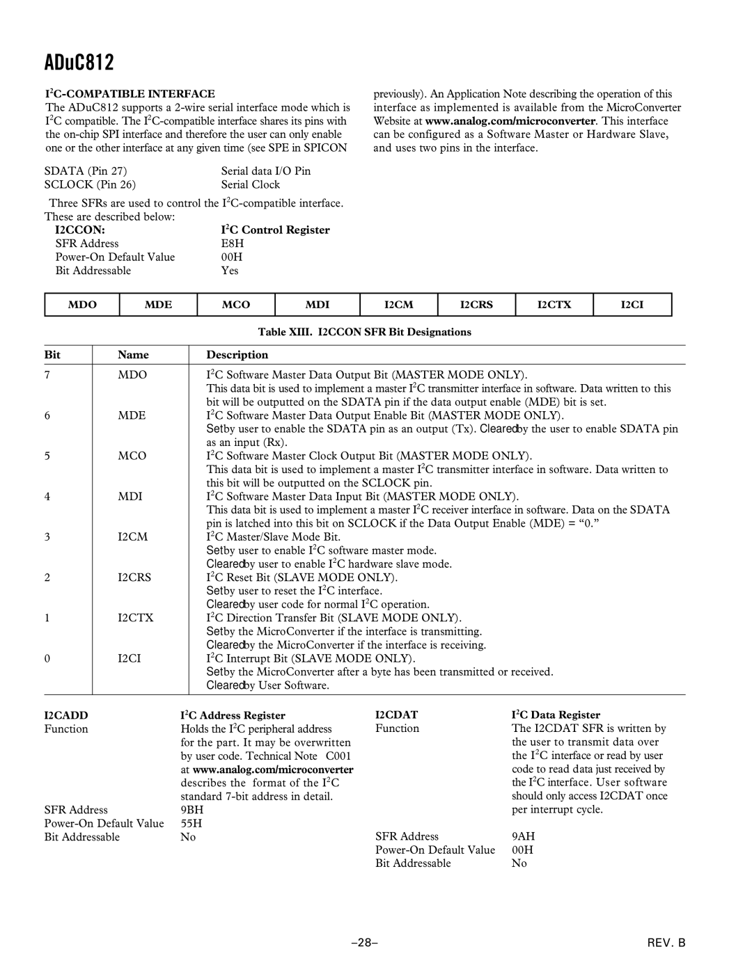
I2CCON: | I2C Control Register |
SFR Address | E8H |
00H | |
Bit Addressable | Yes |
MDO
MDE
MCO
MDI
I2CM
I2CRS
I2CTX
I2CI
|
| Table XIII. I2CCON SFR Bit Designations |
|
|
|
Bit | Name | Description |
|
|
|
7 | MDO | I2C Software Master Data Output Bit (MASTER MODE ONLY). |
|
| This data bit is used to implement a master I2C transmitter interface in software. Data written to this |
|
| bit will be outputted on the SDATA pin if the data output enable (MDE) bit is set. |
6 | MDE | I2C Software Master Data Output Enable Bit (MASTER MODE ONLY). |
|
| Set by user to enable the SDATA pin as an output (Tx). Cleared by the user to enable SDATA pin |
|
| as an input (Rx). |
5 | MCO | I2C Software Master Clock Output Bit (MASTER MODE ONLY). |
|
| This data bit is used to implement a master I2C transmitter interface in software. Data written to |
|
| this bit will be outputted on the SCLOCK pin. |
4 | MDI | I2C Software Master Data Input Bit (MASTER MODE ONLY). |
|
| This data bit is used to implement a master I2C receiver interface in software. Data on the SDATA |
|
| pin is latched into this bit on SCLOCK if the Data Output Enable (MDE) = “0.” |
3 | I2CM | I2C Master/Slave Mode Bit. |
|
| Set by user to enable I2C software master mode. |
|
| Cleared by user to enable I2C hardware slave mode. |
2 | I2CRS | I2C Reset Bit (SLAVE MODE ONLY). |
|
| Set by user to reset the I2C interface. |
|
| Cleared by user code for normal I2C operation. |
1 | I2CTX | I2C Direction Transfer Bit (SLAVE MODE ONLY). |
|
| Set by the MicroConverter if the interface is transmitting. |
|
| Cleared by the MicroConverter if the interface is receiving. |
0 | I2CI | I2C Interrupt Bit (SLAVE MODE ONLY). |
|
| Set by the MicroConverter after a byte has been transmitted or received. |
|
| Cleared by User Software. |
|
|
|
I2CADD | I2C Address Register |
Function | Holds the I2C peripheral address |
| for the part. It may be overwritten |
| by user code. Technical Note ∝C001 |
| at www.analog.com/microconverter |
| describes the format of the I2C |
| standard |
SFR Address | 9BH |
55H | |
Bit Addressable | No |
I2CDAT | I2C Data Register |
Function | The I2CDAT SFR is written by |
| the user to transmit data over |
| the I2C interface or read by user |
| code to read data just received by |
| the I2C interface. User software |
| should only access I2CDAT once |
| per interrupt cycle. |
SFR Address | 9AH |
00H | |
Bit Addressable | No |
REV. B |