ADuC812
Timer/Counter Operation Modes
The following paragraphs describe the operating modes for timer/ counter 2. The operating modes are selected by bits in the T2CON SFR as shown in Table XIX.
Table XIX. TIMECON SFR Bit Designations
RCLK (or) TCLK | CAP2 | TR2 | MODE |
|
|
|
|
0 | 0 | 1 | |
0 | 1 | 1 | |
1 | X | 1 | Baud Rate |
X | X | 0 | OFF |
|
|
|
|
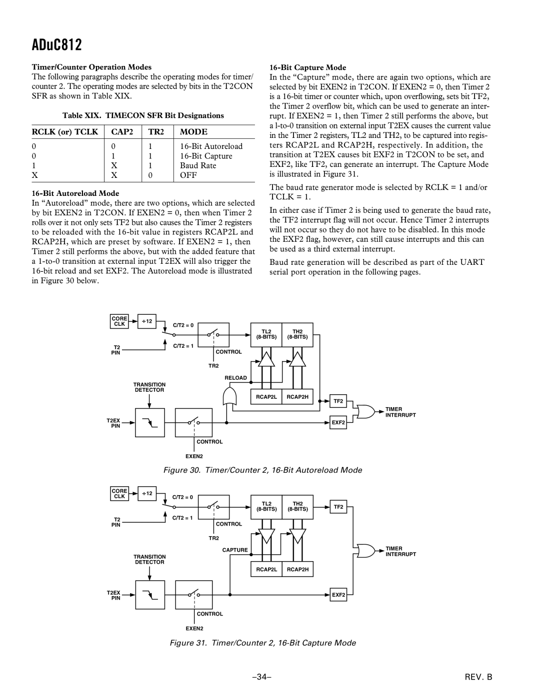
16-Bit Autoreload Mode
In “Autoreload” mode, there are two options, which are selected by bit EXEN2 in T2CON. If EXEN2 = 0, then when Timer 2 rolls over it not only sets TF2 but also causes the Timer 2 registers to be reloaded with the
a
In the “Capture” mode, there are again two options, which are selected by bit EXEN2 in T2CON. If EXEN2 = 0, then Timer 2 is a
The baud rate generator mode is selected by RCLK = 1 and/or TCLK = 1.
In either case if Timer 2 is being used to generate the baud rate, the TF2 interrupt flag will not occur. Hence Timer 2 interrupts will not occur so they do not have to be disabled. In this mode the EXF2 flag, however, can still cause interrupts and this can be used as a third external interrupt.
Baud rate generation will be described as part of the UART serial port operation in the following pages.
CORE | 12 | |
CLK | ||
C/T2 = 0 | ||
T2 | C/T2 = 1 | |
PIN |
|
TRANSITION
DETECTOR
T2EX
PIN
TL2 | TH2 |
CONTROL |
|
TR2 |
|
RELOAD |
|
RCAP2L | RCAP2H |
TF2
![]() EXF2
EXF2 ![]()
TIMER INTERRUPT
CONTROL
EXEN2
Figure 30. Timer/Counter 2, 16-Bit Autoreload Mode
CORE | 12 | |
CLK | ||
C/T2 = 0 | ||
T2 | C/T2 = 1 | |
PIN |
|
TRANSITION
DETECTOR
T2EX
PIN
TL2 | TH2 |
CONTROL |
|
TR2 |
|
CAPTURE |
|
RCAP2L | RCAP2H |
TF2
![]() EXF2
EXF2
TIMER INTERRUPT
CONTROL
EXEN2
Figure 31. Timer/Counter 2, 16-Bit Capture Mode
REV. B |