ADuC812
Mode 0:
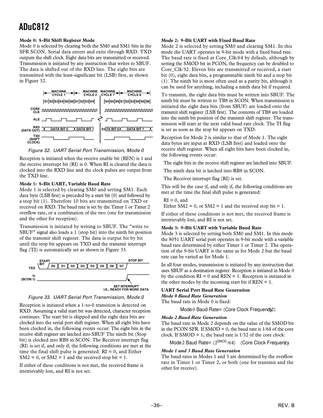
Mode 0 is selected by clearing both the SM0 and SM1 bits in the SFR SCON. Serial data enters and exits through RXD. TXD outputs the shift clock. Eight data bits are transmitted or received. Transmission is initiated by any instruction that writes to SBUF. The data is shifted out of the RXD line. The eight bits are transmitted with the
|
|
|
|
|
|
|
| MACHINE |
| MACHINE | MACHINE | MACHINE | ||||||||||||||||||||||||||||
|
|
|
|
|
|
|
| CYCLE 1 |
|
|
| CYCLE 2 | CYCLE 7 |
|
|
| CYCLE 8 |
|
| |||||||||||||||||||||
|
| S1 S2 S3 S4 S5 S6 S1 S2 S3 S4 |
| S4 S5 S6 S1 S2 S3 S4 S5 S6 | ||||||||||||||||||||||||||||||||||||
CORE |
|
|
|
|
|
|
|
|
|
|
|
|
|
|
|
|
|
|
|
|
|
|
|
|
|
|
|
|
|
|
|
|
|
|
|
|
|
|
|
|
CLK |
|
|
|
|
|
|
|
|
|
|
|
|
|
|
|
|
|
|
|
|
|
|
|
|
|
|
|
|
|
|
|
|
|
|
|
|
|
|
|
|
|
|
|
|
|
|
|
|
|
|
|
|
|
|
|
|
|
|
|
|
|
|
|
|
|
|
|
|
|
|
|
|
|
|
|
|
|
|
|
| |
ALE |
|
|
|
|
|
|
|
|
|
|
|
|
|
|
|
|
|
|
|
|
|
|
|
|
|
|
|
|
|
|
|
|
|
|
|
|
|
|
|
|
|
|
|
|
|
|
|
|
|
|
|
|
|
|
|
|
|
|
|
|
|
|
|
|
|
|
|
|
|
|
|
|
|
|
|
|
|
|
|
| |
RXD |
|
|
|
|
|
| DATA BIT 0 | DATA BIT 1 | DATA BIT 6 | DATA BIT 7 | ||||||||||||||||||||||||||||||
(DATA OUT) |
|
|
|
|
|
| ||||||||||||||||||||||||||||||||||
|
|
|
|
|
|
|
|
|
|
|
|
|
|
|
|
|
|
|
|
|
|
|
|
|
|
|
|
|
|
|
|
|
|
|
|
|
|
|
| |
TXD |
|
|
|
|
|
|
|
|
|
|
|
|
|
|
|
|
|
|
|
|
|
|
|
|
|
|
|
|
|
|
|
|
|
|
|
|
|
|
|
|
(SHIFT |
|
|
|
|
|
|
|
|
|
|
|
|
|
|
|
|
|
|
|
|
|
|
|
|
|
|
|
|
|
|
|
|
|
|
|
|
|
|
|
|
|
|
|
|
|
|
|
|
|
|
|
|
|
|
|
|
|
|
|
|
|
|
|
|
|
|
|
|
|
|
|
|
|
|
|
|
|
|
|
| |
CLOCK) |
|
|
|
|
|
|
|
|
|
|
|
|
|
|
|
|
|
|
|
|
|
|
|
|
|
|
|
|
|
|
|
|
|
|
|
|
|
|
|
|
Figure 32. UART Serial Port Transmission, Mode 0
Reception is initiated when the receive enable bit (REN) is 1 and the receive interrupt bit (RI) is 0. When RI is cleared the data is clocked into the RXD line and the clock pulses are output from the TXD line.
Mode 1:
Mode 1 is selected by clearing SM0 and setting SM1. Each data byte (LSB first) is preceded by a start bit (0) and followed by a stop bit (1). Therefore 10 bits are transmitted on TXD or received on RXD. The baud rate is set by the Timer 1 or Timer 2 overflow rate, or a combination of the two (one for transmission and the other for reception).
Transmission is initiated by writing to SBUF. The “write to SBUF” signal also loads a 1 (stop bit) into the ninth bit position of the transmit shift register. The data is output bit by bit until the stop bit appears on TXD and the transmit interrupt flag (TI) is automatically set as shown in Figure 33.
| START |
|
|
|
|
|
|
| STOP BIT |
| BIT | D0 | D1 | D2 | D3 | D4 | D5 | D6 | D7 |
TXD |
| ||||||||
|
|
|
|
|
|
|
|
|
TI (SCON.1)
SET INTERRUPT
I.E., READY FOR MORE DATA
Figure 33. UART Serial Port Transmission, Mode 0
Reception is initiated when a
If either of these conditions is not met, the received frame is irretrievably lost, and RI is not set.
Mode 2:
Mode 2 is selected by setting SM0 and clearing SM1. In this mode the UART operates in
(1). The ninth bit is most often used as a parity bit, although it can be used for anything, including a ninth data bit if required.
To transmit, the eight data bits must be written into SBUF. The ninth bit must be written to TB8 in SCON. When transmission is initiated the eight data bits (from SBUF) are loaded onto the transmit shift register (LSB first). The contents of TB8 are loaded into the ninth bit position of the transmit shift register. The trans- mission will start at the next valid baud rate clock. The TI flag is set as soon as the stop bit appears on TXD.
Reception for Mode 2 is similar to that of Mode 1. The eight data bytes are input at RXD (LSB first) and loaded onto the receive shift register. When all eight bits have been clocked in, the following events occur:
The eight bits in the receive shift register are latched into SBUF.
The ninth data bit is latched into RB8 in SCON.
The Receiver interrupt flag (RI) is set.
This will be the case if, and only if, the following conditions are met at the time the final shift pulse is generated:
RI = 0, and
Either SM2 = 0, or SM2 = 1 and the received stop bit = 1.
If either of these conditions is not met, the received frame is irretrievably lost, and RI is not set.
Mode 3:
Mode 3 is selected by setting both SM0 and SM1. In this mode the 8051 UART serial port operates in
In all four modes, transmission is initiated by any instruction that uses SBUF as a destination register. Reception is initiated in Mode 0 by the condition RI = 0 and REN = 1. Reception is initiated in the other modes by the incoming start bit if REN = 1.
UART Serial Port Baud Rate Generation
Mode 0 Baud Rate Generation
The baud rate in Mode 0 is fixed:
Mode 0 Baud Rate = (Core Clock Frequency/12)
Mode 2 Baud Rate Generation
The baud rate in Mode 2 depends on the value of the SMOD bit in the PCON SFR. If SMOD = 0, the baud rate is 1/64 of the core clock. If SMOD = 1, the baud rate is 1/32 of the core clock:
Mode 2 Baud Rate = (2SMOD/64) ⋅ (Core Clock Frequency)
Mode 1 and 3 Baud Rate Generation
The baud rates in Modes 1 and 3 are determined by the overflow rate in Timer 1 or Timer 2, or both (one for transmit and the other for receive).
REV. B |