ADuC812
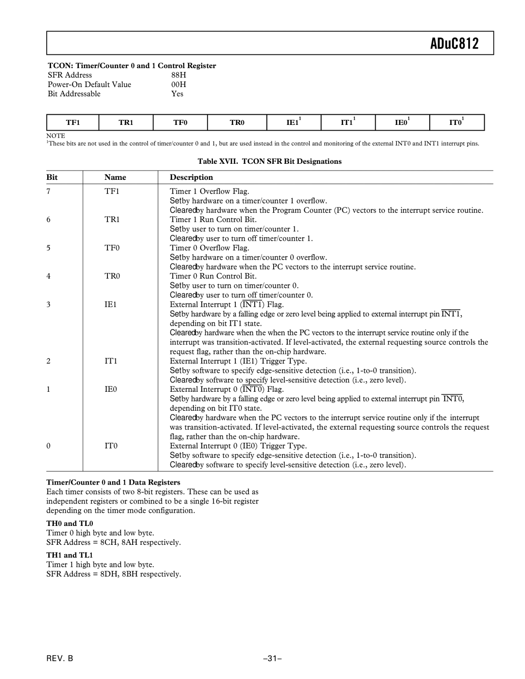
TCON: Timer/Counter 0 and 1 Control Register
SFR Address | 88H |
00H | |
Bit Addressable | Yes |
TF1
TR1
TF0
TR0
IE11
IT11
IE01
IT01
NOTE
1These bits are not used in the control of timer/counter 0 and 1, but are used instead in the control and monitoring of the external INT0 and INT1 interrupt pins.
|
| Table XVII. TCON SFR Bit Designations |
|
|
|
Bit | Name | Description |
|
|
|
7 | TF1 | Timer 1 Overflow Flag. |
|
| Set by hardware on a timer/counter 1 overflow. |
|
| Cleared by hardware when the Program Counter (PC) vectors to the interrupt service routine. |
6 | TR1 | Timer 1 Run Control Bit. |
|
| Set by user to turn on timer/counter 1. |
|
| Cleared by user to turn off timer/counter 1. |
5 | TF0 | Timer 0 Overflow Flag. |
|
| Set by hardware on a timer/counter 0 overflow. |
|
| Cleared by hardware when the PC vectors to the interrupt service routine. |
4 | TR0 | Timer 0 Run Control Bit. |
|
| Set by user to turn on timer/counter 0. |
|
| Cleared by user to turn off timer/counter 0. |
3 | IE1 | External Interrupt 1 (INT1) Flag. |
|
| Set by hardware by a falling edge or zero level being applied to external interrupt pin INT1, |
|
| depending on bit IT1 state. |
|
| Cleared by hardware when the when the PC vectors to the interrupt service routine only if the |
|
| interrupt was |
|
| request flag, rather than the |
2 | IT1 | External Interrupt 1 (IE1) Trigger Type. |
|
| Set by software to specify |
|
| Cleared by software to specify |
1 | IE0 | External Interrupt 0 (INT0) Flag. |
|
| Set by hardware by a falling edge or zero level being applied to external interrupt pin INT0, |
|
| depending on bit IT0 state. |
|
| Cleared by hardware when the PC vectors to the interrupt service routine only if the interrupt |
|
| was |
|
| flag, rather than the |
0 | IT0 | External Interrupt 0 (IE0) Trigger Type. |
|
| Set by software to specify |
|
| Cleared by software to specify |
|
|
|
Timer/Counter 0 and 1 Data Registers
Each timer consists of two
TH0 and TL0
Timer 0 high byte and low byte.
SFR Address = 8CH, 8AH respectively.
TH1 and TL1
Timer 1 high byte and low byte.
SFR Address = 8DH, 8BH respectively.
REV. B |