ADuC812
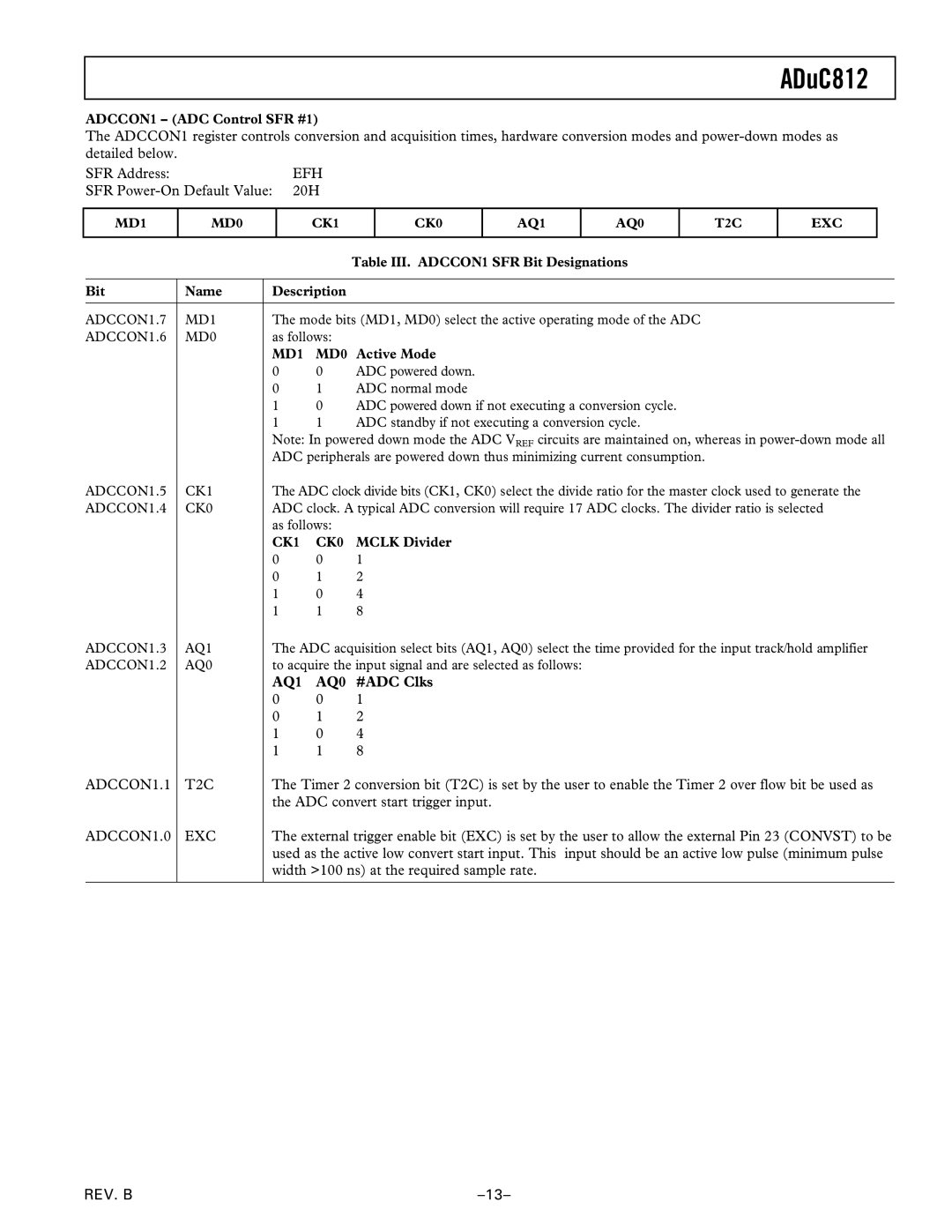
ADCCON1 – (ADC Control SFR #1)
The ADCCON1 register controls conversion and acquisition times, hardware conversion modes and
SFR Address: | EFH |
SFR | 20H |
MD1
MD0
CK1
CK0
AQ1
AQ0
T2C
EXC
|
|
|
| Table III. ADCCON1 SFR Bit Designations |
|
|
|
| |
Bit | Name | Description |
| |
|
|
| ||
ADCCON1.7 | MD1 | The mode bits (MD1, MD0) select the active operating mode of the ADC | ||
ADCCON1.6 | MD0 | as follows: |
| |
|
| MD1 | MD0 Active Mode | |
|
| 0 | 0 | ADC powered down. |
|
| 0 | 1 | ADC normal mode |
|
| 1 | 0 | ADC powered down if not executing a conversion cycle. |
|
| 1 | 1 | ADC standby if not executing a conversion cycle. |
|
| Note: In powered down mode the ADC VREF circuits are maintained on, whereas in | ||
|
| ADC peripherals are powered down thus minimizing current consumption. | ||
ADCCON1.5 | CK1 | The ADC clock divide bits (CK1, CK0) select the divide ratio for the master clock used to generate the | ||
ADCCON1.4 | CK0 | ADC clock. A typical ADC conversion will require 17 ADC clocks. The divider ratio is selected | ||
|
| as follows: |
| |
|
| CK1 | CK0 | MCLK Divider |
|
| 0 | 0 | 1 |
|
| 0 | 1 | 2 |
|
| 1 | 0 | 4 |
|
| 1 | 1 | 8 |
ADCCON1.3 | AQ1 | The ADC acquisition select bits (AQ1, AQ0) select the time provided for the input track/hold amplifier | ||
ADCCON1.2 | AQ0 | to acquire the input signal and are selected as follows: | ||
|
| AQ1 | AQ0 #ADC Clks | |
|
| 0 | 0 | 1 |
|
| 0 | 1 | 2 |
|
| 1 | 0 | 4 |
|
| 1 | 1 | 8 |
ADCCON1.1 | T2C | The Timer 2 conversion bit (T2C) is set by the user to enable the Timer 2 over flow bit be used as | ||
|
| the ADC convert start trigger input. | ||
ADCCON1.0 | EXC | The external trigger enable bit (EXC) is set by the user to allow the external Pin 23 (CONVST) to be | ||
|
| used as the active low convert start input. This input should be an active low pulse (minimum pulse | ||
|
| width >100 ns) at the required sample rate. | ||
|
|
|
|
|
REV. B |