ADuC812
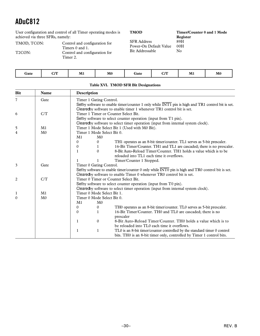
User configuration and control of all Timer operating modes is achieved via three SFRs, namely:
TMOD, TCON: | Control and configuration for |
| Timers 0 and 1. |
T2CON: | Control and configuration for |
| Timer 2. |
TMOD | Timer/Counter 0 and 1 Mode |
| Register |
SFR Address | 89H |
00H | |
Bit Addressable | No |
Gate
C/T
M1
M0
Gate
C/T
M1
M0
|
|
| Table XVI. TMOD SFR Bit Designations | |
|
|
|
| |
Bit | Name | Description |
| |
|
|
| ||
7 | Gate | Timer 1 Gating Control. | ||
|
| Set by software to enable timer/counter 1 only while INT1 pin is high and TR1 control bit is set. | ||
|
| Cleared by software to enable timer 1 whenever TR1 control bit is set. | ||
6 | C/T | Timer 1 Timer or Counter Select Bit. | ||
|
| Set by software to select counter operation (input from T1 pin). | ||
|
| Cleared by software to select timer operation (input from internal system clock). | ||
5 | M1 | Timer 1 Mode Select Bit 1 (Used with M0 Bit). | ||
4 | M0 | Timer 1 Mode Select Bit 0. | ||
|
| M1 | M0 |
|
|
| 0 | 0 | TH1 operates as an |
|
| 0 | 1 | |
|
| 1 | 0 | |
|
|
|
| reloaded into TL1 each time it overflows. |
|
| 1 | 1 | Timer/Counter 1 Stopped. |
3 | Gate | Timer 0 Gating Control. | ||
|
| Set by software to enable timer/counter 0 only while INT0 pin is high and TR0 control bit is set. | ||
|
| Cleared by software to enable Timer 0 whenever TR0 control bit is set. | ||
2 | C/T | Timer 0 Timer or Counter Select Bit. | ||
|
| Set by software to select counter operation (input from T0 pin). | ||
|
| Cleared by software to select timer operation (input from internal system clock). | ||
1 | M1 | Timer 0 Mode Select Bit 1. | ||
0 | M0 | Timer 0 Mode Select Bit 0. | ||
|
| M1 | M0 |
|
|
| 0 | 0 | TH0 operates as an |
|
| 0 | 1 | |
|
|
|
| prescaler |
|
| 1 | 0 | |
|
|
|
| be reloaded into TL0 each time it overflows. |
|
| 1 | 1 | TL0 is an |
|
|
|
| bits. TH0 is an |
|
|
|
|
|
REV. B |
