ADuC812
TIMER/COUNTER 0 AND 1 OPERATING MODES
The following paragraphs describe the operating modes for timer/ counters 0 and 1. Unless otherwise noted, it should be assumed that these modes of operation are the same for timer 0 as for timer 1.
Mode 0
Mode 2
Mode 2 configures the timer register as an
Mode 0 configures an
CORE
CLK
12
C/T = 0
CORE
CLK
P3.4/T0
12
C/T = 0
C/T = 1
TR0
| TL0 | TH0 |
|
| TF0 |
| (5 BITS) | (8 BITS) |
|
| |
|
|
|
| ||
|
|
|
|
|
|
CONTROL
INTERRUPT
P3.4/T0
GATE
P3.2/INT0
C/T = 1
TR0
TL0
(8 BITS)
CONTROL
RELOAD
TH0
(8 BITS)
TF0
INTERRUPT
GATE
P3.2/INT0
Figure 28. Timer/Counter 0, Mode 2
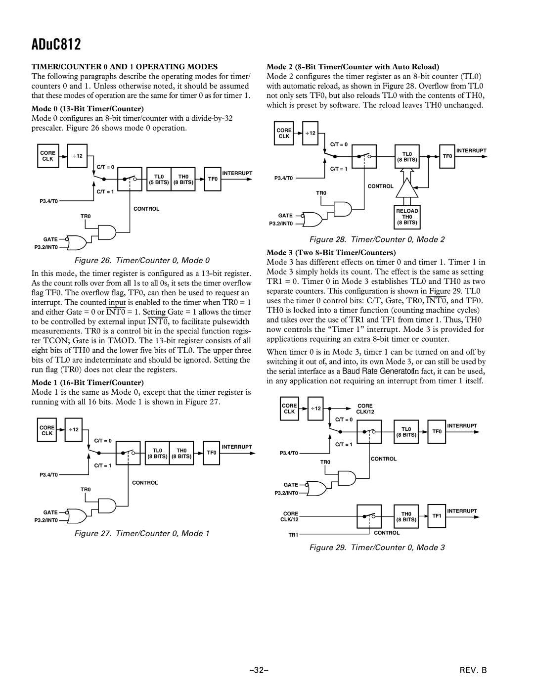
Mode 3 (Two 8-Bit Timer/Counters)
Figure 26. Timer/Counter 0, Mode 0
In this mode, the timer register is configured as a
Mode 1 (16-Bit Timer/Counter)
Mode 3 has different effects on timer 0 and timer 1. Timer 1 in Mode 3 simply holds its count. The effect is the same as setting TR1 = 0. Timer 0 in Mode 3 establishes TL0 and TH0 as two separate counters. This configuration is shown in Figure 29. TL0 uses the timer 0 control bits: C/T, Gate, TR0, INT0, and TF0. TH0 is locked into a timer function (counting machine cycles) and takes over the use of TR1 and TF1 from timer 1. Thus, TH0 now controls the “Timer 1” interrupt. Mode 3 is provided for applications requiring an extra
When timer 0 is in Mode 3, timer 1 can be turned on and off by switching it out of, and into, its own Mode 3, or can still be used by the serial interface as a Baud Rate Generator. In fact, it can be used, in any application not requiring an interrupt from timer 1 itself.
Mode 1 is the same as Mode 0, except that the timer register is running with all 16 bits. Mode 1 is shown in Figure 27.
CORE
CLK
12CORE
CLK/12
C/T = 0
CORE
CLK
12
C/T = 0
TL0 | TH0 |
(8 BITS) | (8 BITS) |
TF0
INTERRUPT
P3.4/T0
TL0
(8 BITS)
C/T = 1
TF0
INTERRUPT
P3.4/T0
C/T = 1
TR0
CONTROL
GATE
P3.2/INT0
TR0
CONTROL
GATE
P3.2/INT0
CORE | TH0 | INTERRUPT | |
TF1 | |||
CLK/12 | (8 BITS) | ||
|
Figure 27. Timer/Counter 0, Mode 1
TR1 |
| CONTROL |
| ||
|
|
Figure 29. Timer/Counter 0, Mode 3
REV. B |