ADuC812
core. This mode allows the ADuC812 to capture a contiguous sample stream at full ADC update rates (200 kHz).
A typical DMA Mode configuration example.
To set the ADuC812 into DMA mode a number of steps must be followed.
1. | The ADC must be powered down. This is done by ensuring |
| MD1 and MD0 are both set to 0 in ADCCON1. |
2. | The DMA Address pointer must be set to the start address of |
| where the ADC Results are to be written. This is done by |
| writing to the DMA mode Address Pointers DMAL, DMAH, |
00000AH | 1 | 1 | 1 | 1 |
| 0 | 0 | 1 | 1 |
| 0 | 0 | 1 | 1 |
| 1 | 0 | 0 | 0 |
| 0 | 1 | 0 | 1 |
000000H | 0 | 0 | 1 | 0 |
STOP COMMAND
NO CONVERSION RESULT WRITTEN HERE
CONVERSION RESULT FOR ADC CH#3
CONVERSION RESULT FOR TEMP SENSOR
CONVERSION RESULT FOR ADC CH#5
CONVERSION RESULT FOR ADC CH#2
and DMAP. DMAL must be written to first, followed by |
DMAH and then by DMAP. |
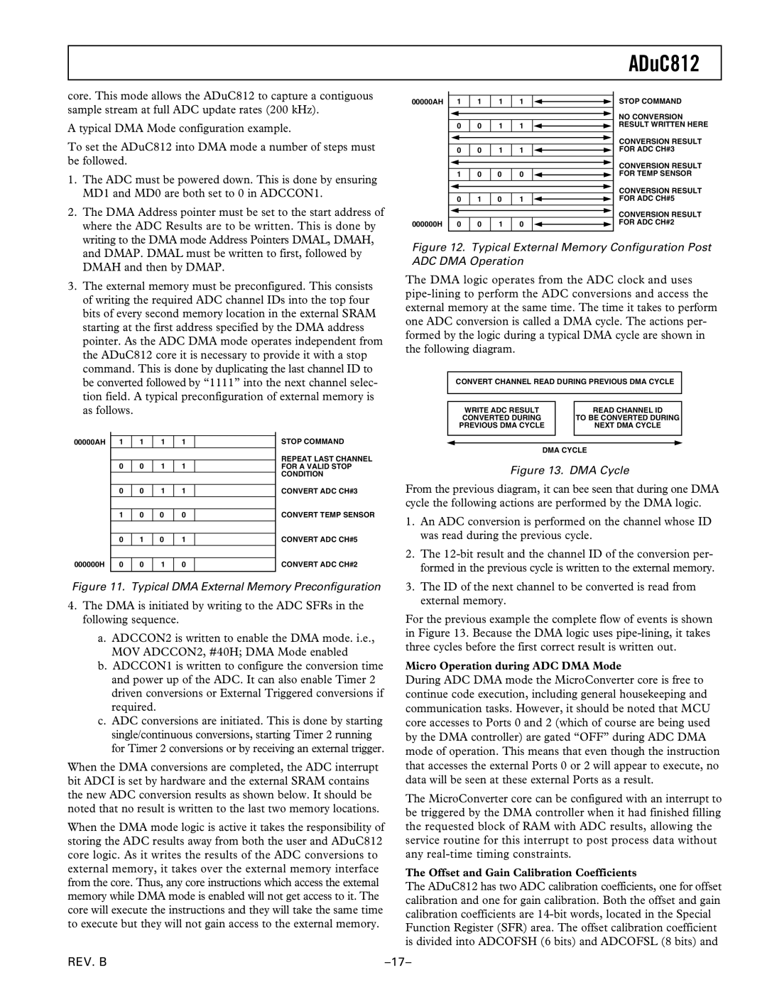
3. The external memory must be preconfigured. This consists |
of writing the required ADC channel IDs into the top four |
bits of every second memory location in the external SRAM |
starting at the first address specified by the DMA address |
pointer. As the ADC DMA mode operates independent from |
the ADuC812 core it is necessary to provide it with a stop |
command. This is done by duplicating the last channel ID to |
be converted followed by “1111” into the next channel selec- |
tion field. A typical preconfiguration of external memory is |
as follows. |
Figure 12. Typical External Memory Configuration Post ADC DMA Operation
The DMA logic operates from the ADC clock and uses
CONVERT CHANNEL READ DURING PREVIOUS DMA CYCLE
WRITE ADC RESULT |
| READ CHANNEL ID |
CONVERTED DURING |
| TO BE CONVERTED DURING |
PREVIOUS DMA CYCLE |
| NEXT DMA CYCLE |
|
|
|
|
|
|
|
|
|
00000AH | 1 | 1 | 1 | 1 |
|
|
|
|
|
|
|
| 0 | 0 | 1 | 1 |
|
|
|
|
|
|
|
| 0 | 0 | 1 | 1 |
|
|
|
|
|
|
|
| 1 | 0 | 0 | 0 |
|
|
|
|
|
|
|
|
|
|
|
|
|
| 0 | 1 | 0 | 1 |
|
|
|
|
|
|
|
000000H | 0 | 0 | 1 | 0 |
|
|
|
|
|
|
|
STOP COMMAND
REPEAT LAST CHANNEL FOR A VALID STOP CONDITION
CONVERT ADC CH#3
CONVERT TEMP SENSOR
CONVERT ADC CH#5
CONVERT ADC CH#2
DMA CYCLE
Figure 13. DMA Cycle
From the previous diagram, it can bee seen that during one DMA cycle the following actions are performed by the DMA logic.
1. | An ADC conversion is performed on the channel whose ID |
| was read during the previous cycle. |
2. | The |
| formed in the previous cycle is written to the external memory. |
Figure 11. Typical DMA External Memory Preconfiguration
4.The DMA is initiated by writing to the ADC SFRs in the following sequence.
a.ADCCON2 is written to enable the DMA mode. i.e., MOV ADCCON2, #40H; DMA Mode enabled
b.ADCCON1 is written to configure the conversion time and power up of the ADC. It can also enable Timer 2 driven conversions or External Triggered conversions if required.
c.ADC conversions are initiated. This is done by starting single/continuous conversions, starting Timer 2 running for Timer 2 conversions or by receiving an external trigger.
When the DMA conversions are completed, the ADC interrupt bit ADCI is set by hardware and the external SRAM contains the new ADC conversion results as shown below. It should be noted that no result is written to the last two memory locations.
When the DMA mode logic is active it takes the responsibility of storing the ADC results away from both the user and ADuC812 core logic. As it writes the results of the ADC conversions to external memory, it takes over the external memory interface from the core. Thus, any core instructions which access the external memory while DMA mode is enabled will not get access to it. The core will execute the instructions and they will take the same time to execute but they will not gain access to the external memory.
3. The ID of the next channel to be converted is read from |
external memory. |
For the previous example the complete flow of events is shown in Figure 13. Because the DMA logic uses
Micro Operation during ADC DMA Mode
During ADC DMA mode the MicroConverter core is free to continue code execution, including general housekeeping and communication tasks. However, it should be noted that MCU core accesses to Ports 0 and 2 (which of course are being used by the DMA controller) are gated “OFF” during ADC DMA mode of operation. This means that even though the instruction that accesses the external Ports 0 or 2 will appear to execute, no data will be seen at these external Ports as a result.
The MicroConverter core can be configured with an interrupt to be triggered by the DMA controller when it had finished filling the requested block of RAM with ADC results, allowing the service routine for this interrupt to post process data without any
The Offset and Gain Calibration Coefficients
The ADuC812 has two ADC calibration coefficients, one for offset calibration and one for gain calibration. Both the offset and gain calibration coefficients are
REV. B |