ADuC812
UART SERIAL INTERFACE
The serial port is full duplex, meaning it can transmit and receive simultaneously. It is also
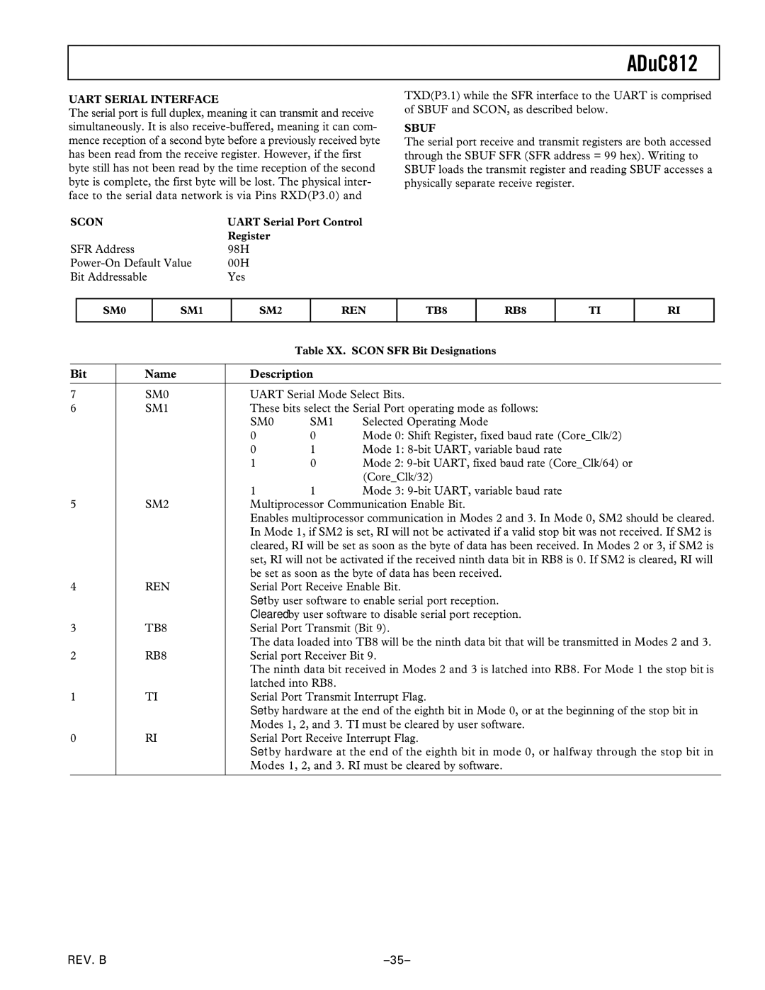
SCON | UART Serial Port Control |
| Register |
SFR Address | 98H |
00H | |
Bit Addressable | Yes |
TXD(P3.1) while the SFR interface to the UART is comprised of SBUF and SCON, as described below.
SBUF
The serial port receive and transmit registers are both accessed through the SBUF SFR (SFR address = 99 hex). Writing to SBUF loads the transmit register and reading SBUF accesses a physically separate receive register.
SM0
SM1
SM2
REN
TB8
RB8
TI
RI
Table XX. SCON SFR Bit Designations
Bit | Name | Description |
| |
|
|
| ||
7 | SM0 | UART Serial Mode Select Bits. | ||
6 | SM1 | These bits select the Serial Port operating mode as follows: | ||
|
| SM0 | SM1 | Selected Operating Mode |
|
| 0 | 0 | Mode 0: Shift Register, fixed baud rate (Core_Clk/2) |
|
| 0 | 1 | Mode 1: |
|
| 1 | 0 | Mode 2: |
|
|
|
| (Core_Clk/32) |
|
| 1 | 1 | Mode 3: |
5 | SM2 | Multiprocessor Communication Enable Bit. | ||
|
| Enables multiprocessor communication in Modes 2 and 3. In Mode 0, SM2 should be cleared. | ||
|
| In Mode 1, if SM2 is set, RI will not be activated if a valid stop bit was not received. If SM2 is | ||
|
| cleared, RI will be set as soon as the byte of data has been received. In Modes 2 or 3, if SM2 is | ||
|
| set, RI will not be activated if the received ninth data bit in RB8 is 0. If SM2 is cleared, RI will | ||
|
| be set as soon as the byte of data has been received. | ||
4 | REN | Serial Port Receive Enable Bit. | ||
|
| Set by user software to enable serial port reception. | ||
|
| Cleared by user software to disable serial port reception. | ||
3 | TB8 | Serial Port Transmit (Bit 9). | ||
|
| The data loaded into TB8 will be the ninth data bit that will be transmitted in Modes 2 and 3. | ||
2 | RB8 | Serial port Receiver Bit 9. | ||
|
| The ninth data bit received in Modes 2 and 3 is latched into RB8. For Mode 1 the stop bit is | ||
|
| latched into RB8. |
| |
1 | TI | Serial Port Transmit Interrupt Flag. | ||
|
| Set by hardware at the end of the eighth bit in Mode 0, or at the beginning of the stop bit in | ||
|
| Modes 1, 2, and 3. TI must be cleared by user software. | ||
0 | RI | Serial Port Receive Interrupt Flag. | ||
|
| Set by hardware at the end of the eighth bit in mode 0, or halfway through the stop bit in | ||
|
| Modes 1, 2, and 3. RI must be cleared by software. | ||
|
|
|
|
|
REV. B |