ADuC812
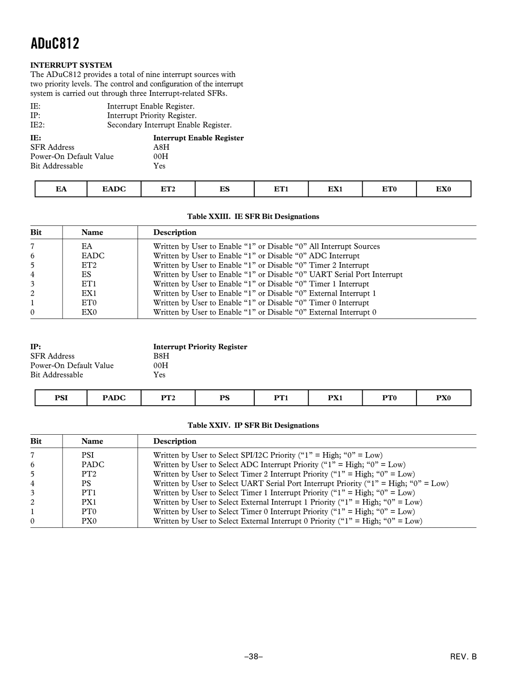
INTERRUPT SYSTEM
The ADuC812 provides a total of nine interrupt sources with two priority levels. The control and configuration of the interrupt system is carried out through three
IE: | Interrupt Enable Register. |
IP: | Interrupt Priority Register. |
IE2: | Secondary Interrupt Enable Register. |
IE: | Interrupt Enable Register |
SFR Address | A8H |
00H | |
Bit Addressable | Yes |
EA
EADC
ET2
ES
ET1
EX1
ET0
EX0
|
|
| Table XXIII. IE SFR Bit Designations |
|
|
|
|
Bit |
| Name | Description |
|
|
|
|
7 |
| EA | Written by User to Enable “1” or Disable “0” All Interrupt Sources |
6 |
| EADC | Written by User to Enable “1” or Disable “0” ADC Interrupt |
5 |
| ET2 | Written by User to Enable “1” or Disable “0” Timer 2 Interrupt |
4 |
| ES | Written by User to Enable “1” or Disable “0” UART Serial Port Interrupt |
3 |
| ET1 | Written by User to Enable “1” or Disable “0” Timer 1 Interrupt |
2 |
| EX1 | Written by User to Enable “1” or Disable “0” External Interrupt 1 |
1 |
| ET0 | Written by User to Enable “1” or Disable “0” Timer 0 Interrupt |
0 |
| EX0 | Written by User to Enable “1” or Disable “0” External Interrupt 0 |
|
|
|
|
IP: |
| Interrupt Priority Register | |
SFR Address |
| B8H | |
00H | |||
Bit Addressable | Yes | ||
PSI
PADC
PT2
PS
PT1
PX1
PT0
PX0
|
| Table XXIV. IP SFR Bit Designations |
|
|
|
Bit | Name | Description |
|
|
|
7 | PSI | Written by User to Select SPI/I2C Priority (“1” = High; “0” = Low) |
6 | PADC | Written by User to Select ADC Interrupt Priority (“1” = High; “0” = Low) |
5 | PT2 | Written by User to Select Timer 2 Interrupt Priority (“1” = High; “0” = Low) |
4 | PS | Written by User to Select UART Serial Port Interrupt Priority (“1” = High; “0” = Low) |
3 | PT1 | Written by User to Select Timer 1 Interrupt Priority (“1” = High; “0” = Low) |
2 | PX1 | Written by User to Select External Interrupt 1 Priority (“1” = High; “0” = Low) |
1 | PT0 | Written by User to Select Timer 0 Interrupt Priority (“1” = High; “0” = Low) |
0 | PX0 | Written by User to Select External Interrupt 0 Priority (“1” = High; “0” = Low) |
|
|
|
REV. B |
