ADuC812
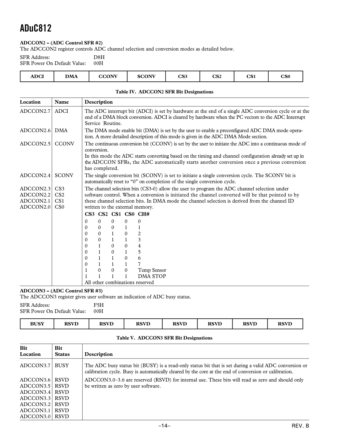
ADCCON2 – (ADC Control SFR #2)
The ADCCON2 register controls ADC channel selection and conversion modes as detailed below.
SFR Address: | D8H |
SFR Power On Default Value: | 00H |
ADCI
DMA
CCONV
SCONV
CS3
CS2
CS1
CS0
|
|
|
| Table IV. ADCCON2 SFR Bit Designations | ||
|
|
|
|
| ||
Location | Name | Description |
|
| ||
|
|
| ||||
ADCCON2.7 | ADCI | The ADC interrupt bit (ADCI) is set by hardware at the end of a single ADC conversion cycle or at the | ||||
|
| end of a DMA block conversion. ADCI is cleared by hardware when the PC vectors to the ADC Interrupt | ||||
|
| Service Routine. |
|
| ||
ADCCON2.6 | DMA | The DMA mode enable bit (DMA) is set by the user to enable a preconfigured ADC DMA mode opera- | ||||
|
| tion. A more detailed description of this mode is given in the ADC DMA Mode section. | ||||
ADCCON2.5 | CCONV | The continuous conversion bit (CCONV) is set by the user to initiate the ADC into a continuous mode of | ||||
|
| conversion. |
|
|
| |
|
| In this mode the ADC starts converting based on the timing and channel configuration already set up in | ||||
|
| the ADCCON SFRs, the ADC automatically starts another conversion once a previous conversion | ||||
|
| has completed. |
|
| ||
ADCCON2.4 | SCONV | The single conversion bit (SCONV) is set to initiate a single conversion cycle. The SCONV bit is | ||||
|
| automatically reset to “0” on completion of the single conversion cycle. | ||||
ADCCON2.3 | CS3 | The channel selection bits | ||||
ADCCON2.2 | CS2 | software control. When a conversion is initiated the channel converted will be that pointed to by | ||||
ADCCON2.1 | CS1 | these channel selection bits. In DMA mode the channel selection is derived from the channel ID | ||||
ADCCON2.0 | CS0 | written to the external memory. | ||||
|
| CS3 | CS2 | CS1 | CS0 | CH# |
|
| 0 | 0 | 0 | 0 | 0 |
|
| 0 | 0 | 0 | 1 | 1 |
|
| 0 | 0 | 1 | 0 | 2 |
|
| 0 | 0 | 1 | 1 | 3 |
|
| 0 | 1 | 0 | 0 | 4 |
|
| 0 | 1 | 0 | 1 | 5 |
|
| 0 | 1 | 1 | 0 | 6 |
|
| 0 | 1 | 1 | 1 | 7 |
|
| 1 | 0 | 0 | 0 | Temp Sensor |
|
| 1 | 1 | 1 | 1 | DMA STOP |
|
| All other combinations reserved | ||||
ADCCON3 – (ADC Control SFR #3)
The ADCCON3 register gives user software an indication of ADC busy status.
SFR Address: | F5H |
SFR Power On Default Value: | 00H |
BUSY
RSVD
RSVD
RSVD
RSVD
RSVD
RSVD
RSVD
|
| Table V. ADCCON3 SFR Bit Designations |
|
|
|
Bit | Bit |
|
Location | Status | Description |
|
|
|
ADCCON3.7 | BUSY | The ADC busy status bit (BUSY) is a |
|
| calibration cycle. Busy is automatically cleared by the core at the end of conversion or calibration. |
ADCCON3.6 | RSVD | |
ADCCON3.5 | RSVD | be written as zero by user software. |
ADCCON3.4 | RSVD |
|
ADCCON3.3 | RSVD |
|
ADCCON3.2 | RSVD |
|
ADCCON3.1 | RSVD |
|
ADCCON3.0 | RSVD |
|
REV. B |