Apple Technician Guide IMac 27-inch, Mid
USA
Basics
Contents About This Guide
Troubleshooting
Symptom Charts
Take Apart
General Information
Bluetooth Board
LCD Panel
Handling the Panel
Vertical Sync Cable Vsync
Video Card
Additional Procedures
Views
Apple Technician Guide About This Guide
Updates
Updated 9 September
Updated 9 August
Feedback
Apple Technician Guide Basics
Overview
Identifying Features
Product Configurations
Safety Precautions
Serial Number Location
New Accessories Magic Trackpad
About the Indicator Light
Pairing the Magic Trackpad
Apple Battery Charger
Batteries
Apple Technician Guide Troubleshooting
General Troubleshooting
Wireless Troubleshooting
Update System Software & Firmware
Troubleshooting Theory
Common Reset Procedures Power On Self Test Post
Hardware vs. Software
Resetting the System Management Controller SMC
Resetting Parameter RAM Pram
Starting Up in Safe Mode
Removing the Battery, Measuring DC Voltage
Diagnostics
Sensors Errors
Sensor
Suggested Action
Logic board this sensor is part Video card assembly
Board Sensor cable if damaged
Sensor Connector Locations Top Side of Logic Board
Sensor Locations
Sensor Connector Location Back Side of Logic Board
Diagnostic LEDs
Location of Diagnostic LEDs
LED Functions
LED #1
LED #2
LED #3
LED Startup Sequence
LED #1 = Power available
LED #1 + LED #2 = Power available, and system is powered on
According to user setup
Board, to enable backlight
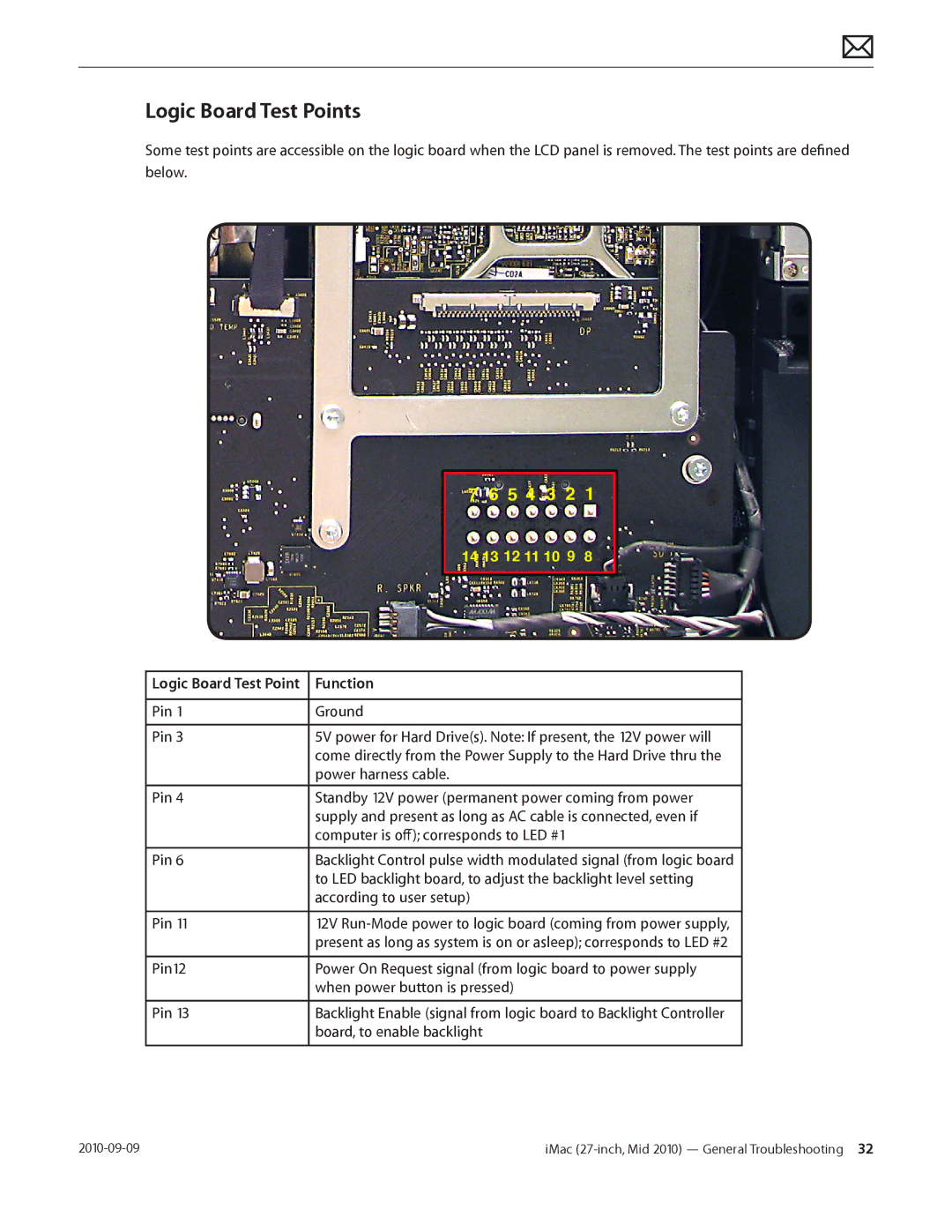
Logic Board Test Points
Function
Functional Overview
Block Diagram
Refer to this diagram to see how modules are interrelated
Symptom Charts
No Power, Dead Unit
Symptoms Quick Check No Power, Dead Unit
Check Result Action Code
To Won’t Start Up symptom
Symptoms Quick Check Won’t Start Up
Safe Boot, Safe Mode?
Sequence and error codes, symbols for
Won’t Start Up
Using a digital multimeter
Go to AirPort Card Kernel
Go to Hard Drive Not
Go to Optical Drive Not
Troubleshooting Shutdown Causes
Intermittent Shutdown
Power-related system shut downs
Powers off during startup
Symptoms Quick Check Intermittent Shutdown
Make sure that power cord is securely attached
Hard drive, update OS with
OS on an external drive. Verify Recognized symptom flow
Supply replacement
Cord and AC outlet, Verify if
X03
M23
X22
P17
Symptoms Quick Check Kernel Panic, System Crashes
Kernel Panic, System Crashes
About You need to restart your computer
Kernel panic messages
Go to Camera Issues or
Go to AirPort/Bluetooth
X01
Go to SD Card Not
Symptoms Quick Check No Video
Go to Backlight Issue/No
No Video
Go to Won’t Start Up
Diagnostic LEDs on edge
Locate diagnostic LEDs on
M03
L03
Symptoms Quick Check Corrupted Video
If issue cannot be seen in the screenshot then
Corrupted Video
Video drivers, software, or video/logic board
M04
Utility Diagnostic and enter
Resolved with replacement LCD panel
Disconnect DisplayPort cable Yes Replace DisplayPort cable
Cable and go to step
Symptoms Quick Check Burnt Smell/Odor
Burnt Smell/Odor
Smfeedback2@apple.com
Uncategorized Symptoms
No Power, Dead Unit symptom flow
Backlight Issue/No Backlight
Symptoms Quick Check Backlight Issue/No Backlight
Panel. Run Apple Service Display Utility to verify
Panel with correct backlight
Logic board and LCD panel
Display
Noise / Unstable Flickering
Symptoms Quick Check Noise / Unstable Flickering
Display Backlight Issue / No Backlight
Run Apple Service Display
Utility to verify the resolution
To Noise/Hum/Vibration
When adjusting brightness level
Symptom flow Issue resolved
LCD Image Issues
Go to pixel anomalies
Go to vertical/horizontal
Lines
Go to non-uniform
Symptoms Quick Check Incorrect/Missing Colors
Incorrect/Missing Colors
Yes Replace LCD panel. Run
L02
Symptoms Quick Check Distorted/Blurred Image
Clean outside of glass panel
Boot from install DVD to determine if a potential
Software issue exists
Reinstalling internal DisplayPort
Pixel Anomalies
L08
Do not replace LCD panel
Symptoms Quick Check Vertical/Horizontal Lines
Vertical/Horizontal Lines
Noise / Unstable Flickering
M24
L04
Service Display Utility to
Issue resolved. If video card
Non-Uniform Brightness / Color
Symptoms Quick Check Non-Uniform Brightness/Color
Service Display Utility. To
Cracked glass panel
Symptoms Quick Check Cosmetic Defects to LCD
Cosmetic Defects
Symptoms Quick Check Drive Not Recognized
Drive No Boot
Error codes, symbols
Hard Drive Not Recognized
Check that the 4 wire Sata Yes Replace any damaged Sata
Power cable carrying 12v
Logic board Reboot computer. Verify if Yes
System boots successfully To user
Hard Drive Read/Write Errors
Go to Optical Drive Read
Mac OS without errors
H04
If computer starts up
H03
Symptoms Quick Check Hard Drive Noisy
Hum/Vibration symptom
Hard Drive Noisy
Refer to Kbase article TS3204 Evaluating
Go to Fan Failures/Thermal
H06
Hard drive
Symptoms Quick Check Drive Not Recognized/Mount
Optical Drive Not Recognized
Symptoms Quick Check Drive Won’t Accept Media
Not Recognized symptom flow
Optical Drive Won’t Accept/Eject Media
Drive Won’t Eject Media
J03
Optical Drive Read/Write Error
Symptoms Quick Check Drive Read/Write Data Error
Replace optical drive Install known-good optical
Drive SATA+Power cable
Issue resolved CD and DVD media. Verify if
Diagnostics, replace optical Drive
Optical Drive Not Performing to Specifications
Symptoms Quick Check Optical Drive Not Performing to
Specifications
Same type to rule out media issue
Running diagnostics, replace
Optical drive
Symptoms Quick Check Optical Drive Noisy J04
Optical Drive Noisy
Test optical drive with different
Compare system with similar
SD Card Will Not Insert Into Slot
Seat into slot Media Cards MMC
Verify if known-good SD card
Tighten SD reader board Now fits in slot Screws. Go to step
Symptom Quick Check SD Card Not Recognized
SD Card Not Recognized
Correctly read and written
AirPort/Bluetooth Issues
Issue. See kBase #HT1365 Airport potential
KBase #HT1365 AirPort Potential source
Interference
Html?path=AirPort/5.0/en
N04
Discoverable mode. Verify if
Bluetooth issues are resolved
M11
Symptoms Quick Check AirPort Card Kernel Panic
AirPort Card Kernel Panic
Ethernet Port/Device Issue
Symptoms Quick Check Ethernet Port/Device Issue
Wireless Input Device Does Not Pair
KBase #HT2532 Mac OS How to change the MTU for
Troubleshooting purposes
Html?path=Mac/10.6
Go to Wireless Input Device
Loses Connection symptom
Connector is damaged
Go to Wireless Input Device Loses Connection symptom
Verify System Preferences/Network settings
Go to step With customer’s mouse Yes
Symptoms Quick Check Apple Remote Inoperable
Apple Remote Inoperable
Responds to Apple Remote
Yes Lens blocked or sensor not
That computer now
M09
Symptoms Quick Check Audio Microphone
Audio Microphone
Inspect microphone cable Yes Replace rear housing
Audio Built-in Speakers Have Distorted Sound
L14
Is normal during playback
Symptoms Quick Check
See kBase #TS1574 Troubleshooting issues
Audio No Audio from Built-in Speakers
Audio
Device, replace audio cable
Output and verify that Internal
Board Go to System Preferences
Go to step Quality is acceptable Set speaker balance 100%
Persists, verify if symptom has
Camera Issues
Symptoms Quick Check Camera Issues
FireWire Device Not Recognized
For external FireWire drives, make sure any
Unplug all FireWire devices
Mode. Verify if FireWire device
Software on User account. Issue
Symptoms Quick Check USB Device Not Recognized
USB Device Not Recognized
Bluetooth not recognized
M15
Wired Keyboard Does Not Function Properly
Symptoms Quick Check Wired Keyboard Does Not
Function Properly
Go to Keyboard Specific Keys Do Not Respond
Go to Optical Drive Won’t
Accept/Eject Media
Keyboard Specific Keys Do Not Respond
Wired Keyboard/Mouse Not Recognized
Input Device Doesn’t Pair symptom flow to
Clean your Mighty Mouse
Troubleshooting Mighty Mouse and determining
Go to USB Device Not
Not Function Properly
Pair with computer
Not charge batteries
Not charge batteries
Trackpad erratic tracking
Apple Wireless Mouse/Magic Trackpad Erratic Tracking
Symptoms Quick Check Apple Wireless Mouse/Magic
Wireless Input Device Loses Connection
K08
Apple Battery Charger Does Not Charge Batteries
Charge Batteries
P01
P10
Was installed in charger
Software is installed and up-to-date, and that
Vary from 80% to almost full
Device is supported with user’s system
Symptoms Quick Check Noise/Hum/Vibration
Stand/Hinge Issues symptom flow
Unstable Flickering symptom flow
Noise/Hum/Vibration
Location table in General
Go to Optical Drive Noisy
Go to Audio Built-in Speakers Have Distorted
Board. Go to Noise/Unstable
From fan housing
Reinstall fans while carefully Yes
Being used When working around an Energized system
P04
Fan Failures / Thermal Issues
Symptoms Quick Check Fan Failures / Thermal Issues
Verify that vents on bottom and back of system
System feels very hot
Stand/Hinge Issues
Symptoms Quick Check Stand/Hinge Issues
X23
Manuals available at http//support.apple.com
Symptoms Quick Check Physical Damage
Physical Damage
Verify if damage caused by user environment
Broken glass
Service Source Take Apart
General Information
Opening the Unit
Required Tools
KBase #HT3452 Hand Tools for Desktop and Portable Repairs
Cleaning Tools Starter Kit
Required Special Tools for Glass Panel
Cleaning & Handling the Glass Panel
Do’s and Don’ts
How to Remove a Broken Glass Panel
Handling a Broken Glass Panel
IMac 27-inch, Mid 2010 Take Apart General Information
IMac 27-inch, Mid 2010 Take Apart General Information
IMac 27-inch, Mid 2010 Take Apart General Information
IMac 27-inch, Mid 2010 Take Apart General Information
Safety
Screw Sizes
Reassembly Steps
Logic Board Handling
Access Door
First Steps
Tools
ESD mat and wrist strap Phillips #2 screwdriver
Removal
Access door
Memory
Remove
ESD mat and wrist strap
Reassembly
Microfoam bag
Glass Panel
Shut down unit Unplug all cables Put on ESD strap
Removal
Reassembly
Set unit in upright position to minimize settling of dust
IMac 27-inch, Mid 2010 Take Apart Glass Panel
Camera
Glass panel
Removal
Reassembly
LCD Panel
Reassembly Note
Remove 8 T10 screws
IMac 27-inch, Mid 2010 Take Apart LCD Panel
Pull display forward slightly to disconnect
Important Panel Handling information
Replacement LCD panel includes Vsync cable
Mylar tape Aluminum tape
Handling the Panel
Important Handle LCD panel by the edges only
Connect the DisplayPort cable
IMac 27-inch, Mid 2010 Take Apart LCD Panel
IMac 27-inch, Mid 2010 Take Apart LCD Panel
Glass panel LCD panel
Pull cable straight out of connector
Vertical Sync Cable Vsync
Peel black insulator to access cable
LED Temp Sensor Cable
Peel back mylar tape securing cable to LCD panel
No tools are required for this procedure
DisplayPort Cable
IMac 27-inch, Mid 2010 Take Apart DisplayPort Cable
Audio Ports and Cable
Torx T10 screwdriver ESD mat and wrist strap
Also help keep audio cable aligned while tightening screws
AirPort Antenna
Magnetized Torx T8 screwdriver ESD-wrist strap and mat
Disconnect antenna cable from AirPort card
AirPort Card
Magnetized Torx T6 screwdriver ESD-wrist strap and mat
Remove 1 T6 screw 922-8579
Hold card by edges and pull it out of the slot
Magnetized Torx T10 screwdriver ESD-wrist strap and mat
AirPort Carrier Board
Glass panel LCD panel AirPort card
Disconnect Airport data cable Remove 2 T10 screws 922-6850
Tools ESD-wrist strap and matt Black stick
AirPort Cable
Glass panel LCD panel AirPort carrier board
Removal
Bluetooth Antenna
Disconnect Bluetooth antenna from the Bluetooth card
Bluetooth Board
Removal
LED Backlight Board
Removal
Power Supply
Voltage
Remove 4 T10 screws Self-tapping, 922- 6850, short S
Longer self-tapping 922- 9593, long L
Route AC power inlet cable over power supply pressure wall
Glass panel LCD panel Power supply
Backlight Pressure Wall
Lift pressure wall off posts in the rear housing
Power Supply/Hard drive Pressure Wall
Lift pressure wall off posts in the rear housing
Replace Kapton tape securing AC inlet cable to pressure wall
Hard Drive
Removal
Orient drive with circuit board facing up as shown
Hard Drive Sensor Cable
Glass panel LCD panel Hard drive
Each hard drive manufacturer has a unique sensor cable
Optical Drive
Torx T10 screwdriver ESD-wrist strap and mat
Removal
IMac 27-inch, Mid 2010 Take Apart Optical Drive
Reassembly
Replace screws in order shown
Tools ESD-wrist strap and mat
Optical Sensor Cable
Glass panel LCD panel Optical drive
Peel up foam gasket to release sensor end of cable
Optical Drive Fan
Remove 1 T10 screw 922-9236
Torx T8 screwdriver ESD-wrist strap and mat Black stick
SD Card Reader
EEE code
Removal
Reassembly
SD Card Reader Cable
Glass panel LCD panel Optical drive Optical drive fan
IMac 27-inch, Mid 2010 Take Apart SD Card Reader Cable
IR Board and Cable
ESD-wrist strap and mat Black stick
Removal
Logic Board
Transfer this jumper if replacing the logic board
Power button CPU fan Skin temp sensor
922-6800, 2 short 922-9237, 2 20mm, medium
Carefully lift board up and out of rear housing
Handling Logic Board
Reassembly
IMac 27-inch, Mid 2010 Take Apart Logic Board
IMac 27-inch, Mid 2010 Take Apart Logic Board
IMac 27-inch, Mid 2010 Take Apart Logic Board
Hard drive temp sensor or HD jumper if SSD-only config
IMac 27-inch, Mid 2010 Take Apart Logic Board
Video Card
Removal
IMac 27-inch, Mid 2010 Take Apart Video Card
Solid State Drive SSD
Torx T8 screwdriver Black stick ESD-wrist strap and mat
Removal
Use a black stick to pry pressure wall off rear housing
Lift pressure wall and SSD drive from rear housing
Reassembly
SSD Data Cable
Disconnect SSD data cable from top of SSD drive
Optical/MXM Pressure Wall
Remove 1 T8 screw on pressure wall
Hard Drive Data Cable
Removal
IMac 27-inch, Mid 2010 Take Apart Hard Drive Data Cable
Optical Drive Data Cable
Replacement Note
Disconnect optical data cable from back side of logic board
Battery
Black stick ESD mat and wrist strap
Make sure battery socket is open and free of dust
Right Speaker
Removal
CPU Fan
Remove 2 T10 shoulder screws
Route sensor cable through clip on fan
Ambient Temp Sensor
Black stick ESD-wrist strap and mat
Release sensor cable from 2 cable clips on CPU fan
Left Speaker
Removal
IMac 27-inch, Mid 2010 Take Apart Left Speaker
Hard Drive Fan
Removal
Mechanism Cover
ESD-wrist strap and mat Magnetized Torx T10 screwdriver
Pry cover off mechanism
Peel up aluminum tape
922-6800
Stand
No preliminary steps are required to remove the stand
Remove the access card
Remove 8 T10 screws 922-8174
Stand the computer upright
Mechanism
Remove 6 T10 screws 922-9238 Lift mechanism off rear housing
Bluetooth Cable
Removal
IMac 27-inch, Mid 2010 Take Apart Bluetooth Cable
Glass panel LCD panel Camera Hard drive Power supply
Camera Cable
Disconnect camera cable #5 from the top of logic board
IMac 27-inch, Mid 2010 Take Apart Camera Cable
Cable, AC/DC Power/Backlight
Sata
Removal
SATA, SSD
Disconnect SSD drive power cable from top of SSD drive
2010-09-09
Refer to the rear housing procedure
Microphone Cable
Rear Housing
When replacing the rear housing follow these important steps
Reinstall 4 screws
Transfer Camera and Reuse Thermal Paste
IMac 27-inch, Mid 2010 Take Apart Rear Housing
Service Source Additional Procedures
Retrieving Mechanism
Overview
Removal
2010-09-09
2010-09-09
Service Source Views
Exploded Views
Exploded View #1
Exploded View #2
Exploded View #3
External Views
Rear View
Ports
Internal Views
Photo of Components below LCD
Photo of Components in the Rear Housing
Logic Board, Front Side
Logic Board, Back Side
Screw Chart
922-9246 922-9239 922-4723
922-9247 922-8579 922-6850
922-9244 922-9593 922-9241
922-9236 922-6800 922-9237
922-9243 922-9242 922-9238
922-8174 922-9488 922-7018
922-7971