Laser Printer MODELHL-1260
Page
Preface
Chapter General
Chapter III Electrical System
Iii
Chapter V Maintenance and Servicing
Specifications
Features
OPC
Printing system Photosensitive drum
Plain Paper
Effective printing area
Envelope
OCR-A OCR-B
2M bytes expandable to 26M bytes
RAM
Laser Safety 110 ~ 120V Model only
Safety Information
Additional Information
Cdrh Regulations 110 ~ 120V Model only
External Views
Parts of the Printer
Cross Sectional View
Storage of Sealed EP-ED Cartridges
Storage and Handling of EP-ED Cartridges
Storage of Unsealed EP-ED Cartridges
Basic Operations
Mechanical Configuration
Main Drive
Timing for two consecutive prints on A4 paper
Basic Sequence of Operations
Optical sensor Scanner motor
LASER/SCANNER System
To external device Main PCB
Scanner driver Collimator lens Scanning mirror
Outline
Image Formation System
Printing Process
Electrostatic latent image formation stage
Scanning exposure
Primary charge
+ + +
Development
Developing stage
Separation
Transfer stage
Transfer
Reference
Fixing
Drum cleaning stage
Drum cleaning
Fixing stage
PCB
Operation
PCB
Paper PICK-UP/FEED System
Stby Print
Cassette Feed
MP Tray Feed
Main motor Paper feed Motor Registration Sensor
Paper Jam Detection
Main motor Pick-up solenoid Registration Sensor
Jam check Jam inside
Jam rear
Main PCB
Main PCB Block Diagram
SLOT1 4MB SLOT2 2MB SLOT3 1MB
Video Controller Circuit
III
Memory map
Simm map
B48K158
Engine Controller Circuit
Main PCB Circuit
Paper Feed Drive Circuit
SW PCB
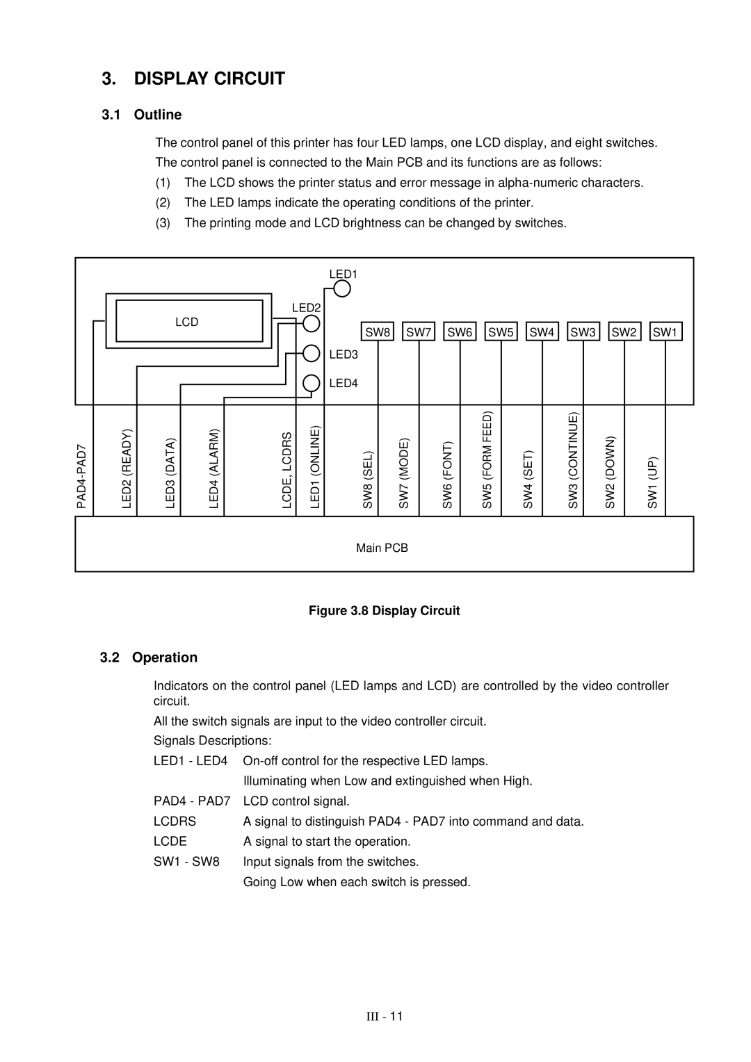
Display Circuit
Protection Functions
LOW-VOLTAGE Power Supply Assy
Low-Voltage Power Supply PCB Block Diagram
HIGH-VOLTAGE Power Supply Assy
10 High-Voltage Power Supply Block Diagram
11 High-Voltage Power Supply Block Diagram
Chapter IV Mechanical System
Prinnter Disassembling Procedure
Side Cover L
Configuration
Printer Body
Toner Cartridge Lid
Upper Cover Assy, Rear Cover Assy
Font Cover Assy
Upper cover assy, rear cover assy
Changeover guide, jam remove cover
Side Cover R
Remove the side cover R by releasing the 4 hooks
Remove the MIO box
DC Fan Motor
Main PCB
Remove the Simm replace lid
Remove the main PCB assy
Hooks Control panel unit
Control Panel Unit
Cartridge Stopper Assy
Scanner Unit
Paper Feed Chassis Unit
Remove the paper feed chassis unit
Separation Pad Assy
Remove the spring from the separation pad assy
Feed /Size-SW PCB Assy
Side-Switch Spring
Pull out the size-switch spring
MP PE Sub Actuator
MP Paper Detection Actuator
Regist sensor actuator
PE Sensor Actuator MP
Roller Holder
Tray Sensor Holder
Remove the gear Loosen and pull out the 2 screws
Paper Pick-up Roller Assy, Bearing
Paper Feed Motor Assy
Paper Pick-up Solenoid
Remove each solenoid by loosening their screw
MP Tray Assy
MP Tray Cover
Remove the 2 fixing bushes Remove the MP tray assy
Paper Path Separation Plate, Paper Path Separation Film
Remove them from the paper feed guide lower by bending them
Latch
Loosen a screw and remove the fixing PCB assy
Paper delivery actuator Fixing unit cover
Transfer Unit
DC Gear Holder Assy
PS Switch Wire, Remote Switch
Loosen the 4 screws on the top
High-Voltage Power Supply PCB
Low-Voltage Power Supply PCB Assy
Remove the PS switch wire Loosen the 2 screws on the side
Paper Tray
Toner Cartridge EP-ED Cartridge
Remove the toner cartridge from the body
Screws Tray gear holder Gear 56T link
Consumable Parts Standard Endurance Table
Periodical Replacement Parts
Without prior notice
Compression spring scale
List of Standard Tools
Snap-ring pliers, ext
List of Lubricants and Cleaners
Initial Check
Introduction
Test Printing and Mechanical Check
Basic Procedure
Test Printing
Image Defect Examples
Image Defects
Light
Troubleshooting Image Defects
Dark
Completely blank
All black
Dirt on back of paper
Polka dots
Replace the fixing unit
Error
Possible cause Step Check Result Remedy
Check the toner image on the drum
White vertical streaks
Dropout
Poor fixing
Faulty registration
No DC power supplied
Troubleshooting of Malfunctions
Is the pulse of 4KHz output? Buzzer
Press the Mode switch and select Advanced mode Main PCB
Step Check Result Remedy Upper cover
14 no Cartridge is displayed
16 Toner Empty is displayed
Motor Malf is displayed The main motor rotation disabled
High-voltage Yes Replace the high-voltage Off?
Scanner unit
On again?
17 41 Print Check is displayed
Paper Jams
Troubleshooting Paper Transport Problems
1a Paper pick-up block Pick miss
1b Paper pick-up block Oblique feed jam
Recommended type of paper
Clean the static-charge
Step Check Result Remedy Print Paper
Instruct the user to use
Double feeding
Incomplete Paper Feed
Operation
Line Inspection Mode Procedure
3 4 5 6 7
Flash memory check
Switch to check the font cartridge
Turn off the power
Press
Video Controller Dram Address Corresponding Table
Dram Test
Replace the Dram on the Main PCB Replace the Simm
Operator Call Messages
Status Message List
Error Message Meaning Action
Error Messages
Card Full
Service Call Message Meaning Action
Service Call Messages
Error Turn off the printer. Wait
Appendix 1. Engine Block Diagram
Appendix 2. Paper Feed/Size-SW PCB Circuitry Diagram 1/1
Appendix 3. Main PCB Circuitry Diagram 1/8
Appendix 4. Main PCB Circuitry Diagram 2/8
Appendix 5. Main PCB Circuitry Diagram 3/8
Appendix 6. Main PCB Circuitry Diagram 4/8
Appendix 7. Main PCB Circuitry Diagram 5/8
Appendix 8. Main PCB Circuitry Diagram 6/8
Appendix 9. Main PCB Circuitry Diagram 7/8
Appendix 10. Main PCB Circuitry Diagram 8/8
Appendix 11. Control Panel PCB Circuitry Diagram 1/1
Appendix 12. Scanner LD PCB Circuitry Diagram 1/1
Laser Printer
Page
Preface
Storage and Handling of EP-ED Cartridges
Refer to HL-1260 P.III-9
List of Lubricants and Cleaners
Chapter I General
Executive
Letter
Legal
ISO
B5 ISO
COM-10
OCR-A OCR-B
4M bytes expandable to 66M bytes
Safety Information
Additional Information
HL-1660
Paper PICK-UP/FEED System
MP Tray Feed
Main motor Pick-up solenoid Registration Sensor
Stby Print
Jam rear
Font Cartridge IC Card Pcmcia Asic HG51CS265FD
SLOT1 4MB SLOT2 1MB
ROMOA, OB, 1A, 1B ROM1B
Main PCB HL-1260e
Main PCB HL-1660
PCB
Main PCB
Circuit
Chapter IV Mechanical System
Printer Disassembling Procedure
Screws yellow Simm replace lid
Remove the main PCB assy
Scanner Unit
Scanner fan motor
Paper Tray
Number of print
Malfunction of LCD display on the control panel
No DC power supplied
Malfunction of control panel LED lamps
Malfunction of buzzer
Malfunction of control panel switches
Cover Open is displayed even if the upper cover is closed
14 no Cartridge is displayed
Step Check Result Remedy
No paper pick-up from cassette or MP tray
Motor Malf is displayed The main motor rotation disabled
Reference Value
16 52 Scanner Malf is displayed
14 50 Fuser Malf is displayed
17 41 Print Check is displayed
Wrong size of paper was Load the requested size
Upper cover Close the cover. See M-6 Printer is open
Error Messages
Equipping DX for 1260/e Use DX for HL-1660
Equipping LT for 1260/e Use LT for HL-1660
Service
Error Turn off the printer. Wait a
Service
Software1 Trap Turn off the printer. Wait a
Scanner Unit
Appendix 3. Main PCB Circuitry Diagram 1/7
Appendix 4. Main PCB Circuitry Diagram 2/7
Appendix 5. Main PCB Circuitry Diagram 3/7
Appendix 6. Main PCB Circuitry Diagram 4/7
Appendix 7. Main PCB Circuitry Diagram 5/7
Appendix 8. Main PCB Circuitry Diagram 6/7
Appendix 9. Main PCB Circuitry Diagram 7/7
Appendix 11. Scanner LD PCB Circuitry Diagram 1/1
PR99087
Paper Feeder
Release Plate L ADD
Paper Feeder
Release Plate L ADD
No. PR98202 / PR99087
Model HL-1660e 54T-U03-630 NO. PR98202 / PR99087
TI NO. PR99087
085310815
UH1835001
UH1565001
087320616
TI no -P049 / PR99087
ADD
LT-2000 54T
UH2906000
UH2901001
UH2952001
UH2905000
Parts Reference List
Revision No. marked on a printed circuit board
B48K056 201 a
Contents
Power Cords & Harnesses
Power Cords & Harnesses
TI No.96-P035 / PR98309
Control Panel
Control Panel REF.NO Code QTY Description Symbol Remark
TI No.96-P013 /96-P046
B48K234
TI No.PR97114
Main PCB, Others
TI No.96-P013 / 96-P046
Main PCB, Israel
TI No. PR97114
Main PCB, Israel
TI No.96-P033
HIGH-VOLTAGE Power Supply
Covers
Covers REF.NO. Code QTY Description Remark
TI No.96-P077 / 97-P021
Paper Tray
TAPTITE, CUP S M3X10
TI no -P049 / PR97037 / PR97131 / PR98202
Paper Feeder REF.NO Code QTY Description Remark
TI No.PR97148, PR98054, PR98061
TI No.96-P018
SCN Harness 4P
TI No.96-P044 / 97-P009
Packing Materials
Documents
43-D,N,O
TI no -P066
NO. PR98047
Adjusting Tool KIT Tool no Tool Name Remark
Brother Laser Printer
USER’S Guide
Compilation and Publication
Trademarks
Laser Printer
HL-1260e/HL-1660
Definitions of Warnings, Cautions, and Notes
Table of Contents
Before Working with the Printer
Switches in Normal Mode
Options
Appendix-1
Index
Important About the Interface Cable
Important Information Regulations
Cdrh Regulations 110-120 V model only
Laser Safety 110-120 V model only
IEC 825 220-240 V model only
Radio Interference220-240 V model only
Wiring Information For U.K. only
For Your Safety
Green and Yellow Earth Blue Neutral Brown Live
Declaration of Conformity Europe
About this Manual
Chapter General
USER’S Guide
For Windows 3.1 user
About Chapters on the Floppy Disk
About this Printer
Features
Five Emulation Modes
Universal Paper Cassette and Manual Loading
Three Interfaces
Automatic Interface Selection
Scalable and 12 Bitmapped Fonts
Automatic Emulation Selection
Data Compression Technology
Memory Expansion
OCR-A OCR-B
Bar Code Print
Power Save Mode
Toner Save Mode
High Speed Printing with Microsoft Windows 95 / Windows
Reprint Function
Saving User Settings
Flash Memory Card and HDD Card
Options
Checking the Components
Before Using the Printer
Printer Carton
Toner Cartridge
Toner Cartridge
Front View
General View
Operating and Storage Environment
Power Supply
Environment
Opening and Closing the Printer
Setting UP the Printer
Removing the Protective Parts
Removing the Protective Parts
No Cartridge
Installing the Toner Cartridge
10 Rocking the Toner Cartridge
12 Pulling Out the Sealing Tape
Toner Empty
Loading Paper in the Paper Cassette
14 Removing the Paper Cassette
15 Switching the Adjustment lever by Paper Size
17 Adjusting the Paper Cassette Sizes
Getting Started
20 Placing Paper on the Multi-purpose Tray
Connecting the Printer to Your Computer
21 Connecting the Printer and Computer
Turning the Printer On and Off
Plugging in the Power Cord
Self Test
Pressing the Power Switch
LJ Ready 001P T1
Printing the Test Patterns or Lists
Print Fonts P
Print Fonts C
ABC
Checking the Printed Test Pattern or Demo
Software Compatibility
Chapter Before Working with the Printer
USER’S Guide
GL Ready
Automatic Emulation Selection
LJ Ready
BS Idle
USER’S Guide
OFF
Automatic Interface Selection
USER’S Guide
About the Control Panel
Adjusting the Control Panel Angle
Selecting the Local Language Display
Switch Operation in Normal and Shift Modes
Using the Panel Switches
User Settings
Printer Settings
Factory Settings
Print Media
Paper Handling
Paper Size
USER’S Guide
Envelope Information
Using Envelopes
Envelopes
Load Paper
Cassette Feed
Cassette Feed
Manual Feed
Face Up Print Delivery
Face Down Print Delivery
Display
Display and Lamps
Print
Idle
Busy
Sleep
FF Pause
Reset to User Settings
Data
Lamps
SEL Switch
Switches in Normal Mode
UP or Down Switch
SET Switch
Mode Switch
Interface Mode =PARALLEL High SPEED=ON
Format Mode Orientation ORI=PORTRAIT
Card List
Mode Switch Settings in BR-Script 2 Mode
Error Print Error PRINT=OFF
Graphics Mode PEN Setting SETTING=PEN1
Mode Switch Settings in HP-GL Mode
Legal
Basic Operation Procedures
Operation Example Selecting the Parallel Interface
=AUTO
=PARALLEL
=OPTION
Interface Mode
BI-DIR=ON
High SPEED=ON
Robust Xon =OFF
Dtrer =ON
ORI=PORTRAIT
Format Mode
Auto Skip =ON
Auto LF =OFF
Auto CR =OFF
Auto Wrap =OFF
Format Mode
TOP M
Paper =LETTER
Left M
Right M = 80C P
USER’S Guide
Graphics Mode
SETTING=PEN1
PEN Setting
Character SET
Alternate SET
Standard SET
Ansi Ascii
APT Setting
Resolution
HRC Setting
Setting
HRC =LIGHT
APT =OFF
APT =ON
HRC =OFF
Print Overrun
Protection
PROTECT=LEGAL
PROTECT=AUTO
PROTECT=LETTER
PROTECT=A4
Format Card
Save
Card List
Delete
Download Font
Save Data
Save Macro
Primary Font
SET KEY -- END
Macro ID=#####
USER’S Guide
Font ID=#####
Delete the selected ID macro
FF SUPPRESS=OFF
SET--DELETE ALL
Lock PANEL=OFF
Auto FF=ON
Incorrect
LOCK=OFF
LOCK=ON
Pass NO=
Wait TIME= 1s
Auto FF=OFF
Error Print
FONT=LJ4
BUZZER=ON
BUZZER=OFF
FONT=ALL
Print Density
Save Settings
Counter
Symbol SET
Font Switch
Setting the Font and Symbol Set in the HP LaserJet 4+ Mode
Primary Font Secondary Font
Secondary Font
Permanent Font
Internal Font
Slotfont
Slotfont B
Brougham Reg p
Roman
PITCH=
Table Print
Select Font
Internal Font
Brougham Reg
Brougham
PITCH=
US Ascii
OCR-B
BR Symbol
Lettergothic
OCR-A
Danish
ISO LATIN1 German
ISO LATIN2 UK Ascii
ISO LATIN5 French
Form Feed
Form Feed Switch Reprint Switch
USER’S Guide
Continue Switch
Shift Switch
Switches in Shift Mode
Epson FX-850
Emulation Switch
Auto
HP-GL
Keep PCL=OFF
EPSON/IBM=EPSON
About Emulation Modes
USER’S Guide
Toner SAVE=OFF
Economy Switch
Toner SAVE=ON
Feeder Switch
FEEDER=TRAY1
FEEDER=MP Tray
FEEDER=TRAY2
MP First
AUTO=T1MP
MP SIZE=LETTER
MP Tray Setting
Media Type
Paper IN=CONT
DUPLEX=OFF
Regular
BIND=LONG
Binding
Copy PAGES=
Copy Switch
Factory Settings
Reset Switch
Reset Printer
Reset Setting
List of Factory Settings
Reset to User Settings
Reset to Setting #
Reset to Factory Settings
Mode Interface Mode =AUTO
EPSON, & IBM Paper Left M Right M TOP M Bottom M
Offset OFFSET=0
Input Buffer Counter
Toner Save Mode Toner SAVE=OFF Power Save Mode Power SAVE=ON
Test Switch
Demo
Print Fonts
HEX Dump Mode
Control Panel
Loading Paper from the Lower Paper Cassette
Lower Tray Unit LT-1200/LT-1600
Font CARTRIDGE/CARD, Flash MEMORY/HDD Card
MCM33708DFB
See Printing the Test Pattern or Font List in Chapter
Selecting the Optional Fonts
Find the font slot and font ID number on the list
Modular I/O Card
Installing the MIO Card
RAM Expansion
Mitsubishi MH1M32ADJ-7
Removing the Left Side Cover
Installing the SIMMs
Duplex Unit DX-1200/DX-1600
For Duplex
Toner Cartridge
Maintenance
Toner Empty Message
Replacing the Toner Cartridge
Cleaning the Anti-Static Teeth
USER’S Guide
Cleaning the Printer Exterior
Cleaning
Cleaning the Paper Cassette
Cleaning the Printer Interior
Cleaning the Paper Access Cover Transfer Guide
Operator Call Messages
Troubleshooting
No DX Tray
Manual Feed
Check Font
No DX Unit
Memory Full
Error Messages
Buffer Error
Line Error
XX Size Error
Card W Error
Simm Error
MIO Error
Service Call Messages
Paper Jam
Possible Problems
Paper Jam at Paper Exit
JAM Rear
Paper Jam at Rear Access Cover
Paper Jam at Fixing Roller
JAM Inside
Paper Jam at the Paper Access Cover Inside the Printer
Paper Jam at Paper Cassette
JAM Trays
White Stripes or Faint Images
Unsatisfactory Printouts
Removing the Toner Cartridge
10 Distributing the Toner Evenly
11 Dark Stripes or Toner Stains
12 White Spots
Black
HRC = OFF HRC = Medium
BBS
Printing
Printer Specifications
CPU
Functions
Electrical and Mechanical
Option
Paper Specifications
Paper
Paper Types to Avoid
Labels and Overhead Transparencies
Pin Assignment
Interface Specifications
Interface Connector
Bi-directional Parallel Interface
Acknlg OUT
Signal Description
Signal Printer Pin No Computer Pin No
Interface Connectors
Standard Specifications
RS-232C Serial Interface
Signal Name IN/OUT Explanation Frame Ground
Printer Male
OCR Symbol Sets
SYMBOL/CHARACTER Sets
HP LaserJet 4+ Mode
PC-8 10U PC-8 D/N 11U PC-850 12U PC-852 17U
Appendix-17
Legal 1U Ventura Math 6M Ventura Intl 13J Ventura US 14J
PS Math 5M PS Text 10J Math-8 8M Pi Font 15U
MS Publishing 6J Windows 3.0 9U Desktop 7J MC Text 12J
Symbol 19M Windings 579L
US Ascii
Epson Mode
PC-8 PC-8 D/N PC-850 PC-852
PC-860 PC-863 PC-865 PC-8 Turkish
IBM Mode
Appendix-26
HP-GL Mode
FRENCH/GERMAN Scandinavian SPANISH/LATIN JIS Ascii
ROMAN8 EXT ISO IRV ISO Swedish ISO Swedishn
ISO Norway ISO German ISO French ISO U.K
ISO Italian ISO Spanish ISO Portuguese ISO Norway
These symbol sets are variations of the Roman-8 symbol set
Appendix-33
Appendix-34
Appendix-35
PCL Command Sets
Quick Reference of Commands
Appendix-37
Appendix-38
Appendix-39
Appendix-40
Appendix-41
Appendix-42
Appendix-43
Appendix-44
Appendix-45
Appendix-46
Appendix-47
Appendix-48
Ccitt G3/G4 and Tiff original command
Appendix-50
APT
@PJL Enter Language = PCL
Horizontal 1200-dpi Image Format ModeRaster Graphic Mode
Block data is composed as follows
Appendix-54
Bezier Relative
HP-GL/2 Command Sets
Appendix-56
DEC HEX
Printer Job Language Commands Syntax
BEL
Epson FX-850 Mode
Appendix-59
Appendix-60
IBM Proprinter XL Mode
Appendix-62
Appendix-63
Appendix-64
Appendix-65
Print Bar Codes or Expanded Characters
Bar Code Control
Appendix-67
Appendix-68
Isbn UPC-E
Appendix-70
Check digit
FIM
Lprint CHR$12 END
Index
Index-2
Paper access cover
Symbol set 4-60,Appendix-14