ADDITIONAL ACCESSORIES
1 | 2 | 3 |
4 | 5 | 6 |
7 | 8 | 9 |
: | A | B |
C | D | E |
F |
| G |
H | I | J |
K | L | M |
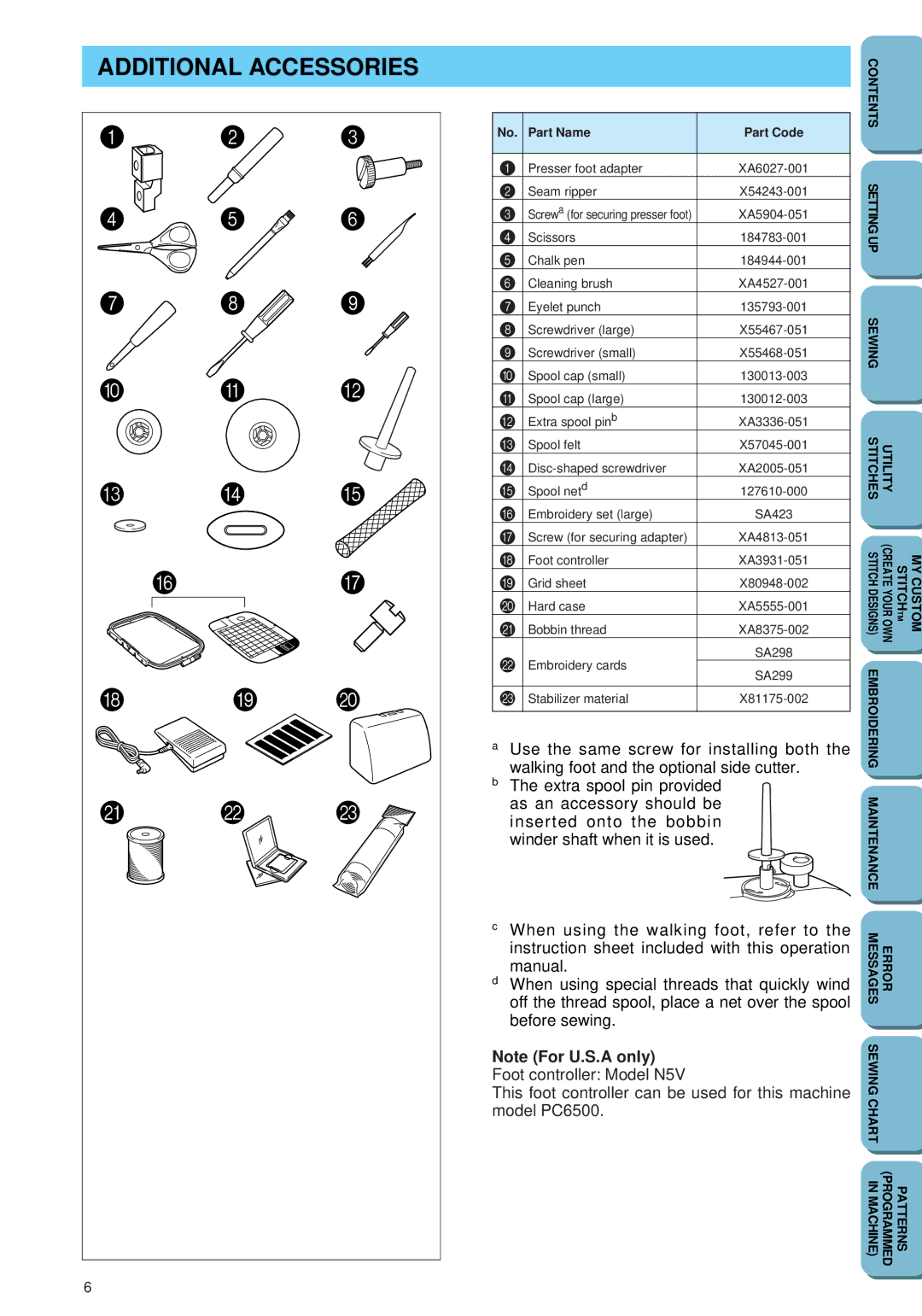
No. | Part Name | Part Code | |
|
|
| |
1 | Presser foot adapter | ||
2 | Seam ripper | ||
3 | Screwa (for securing presser foot) | ||
4 | Scissors | ||
5 | Chalk pen | ||
6 | Cleaning brush | ||
7 | Eyelet punch | ||
8 | Screwdriver (large) | ||
9 | Screwdriver (small) | ||
0 | Spool cap (small) | ||
A | Spool cap (large) | ||
B | Extra spool pinb | ||
C | Spool felt | ||
D | |||
E | Spool netd | ||
F | Embroidery set (large) | SA423 | |
G | Screw (for securing adapter) | ||
H | Foot controller | ||
I | Grid sheet | ||
J | Hard case | ||
K | Bobbin thread | ||
L | Embroidery cards | SA298 | |
SA299 | |||
|
| ||
|
|
| |
M | Stabilizer material | ||
|
|
|
aUse the same screw for installing both the walking foot and the optional side cutter.
bThe extra spool pin provided as an accessory should be inserted onto the bobbin winder shaft when it is used.
CONTENTS |
|
|
SETTING UP |
|
|
SEWING |
|
|
STITCHES | UTILITY |
|
STITCH DESIGNS) | STITCHTM (CREATE YOUR OWN | MY CUSTOM |
EMBROIDERING |
|
|
MAINTENANCE |
|
|
6 |
c | When using the walking foot, refer to the | MESSAGES | ERROR |
| instruction sheet included with this operation | ||
|
|
| |
d | manual. |
|
|
When using special threads that quickly wind |
|
| |
| off the thread spool, place a net over the spool |
|
|
| before sewing. | SEWING |
|
Note (For U.S.A only) |
| ||
|
| ||
Foot controller: Model N5V |
|
| |
This foot controller can be used for this machine | CHART |
| |
model PC6500. |
| ||
|
| ||
|
| IN MACHINE) | PATTERNS (PROGRAMMED |