Chapter 1: Introduction
Appendix A, Specifications, contains information on functionality and operating specifications, connector pinouts, environmental requirements, and physical properties.
Appendix B,
Appendix C, Optional Installations and Mode Switch Bank Settings, describes how to install optional Fast Ethernet Interface Modules and how to set the Mode Switch.
1.3OVERVIEW
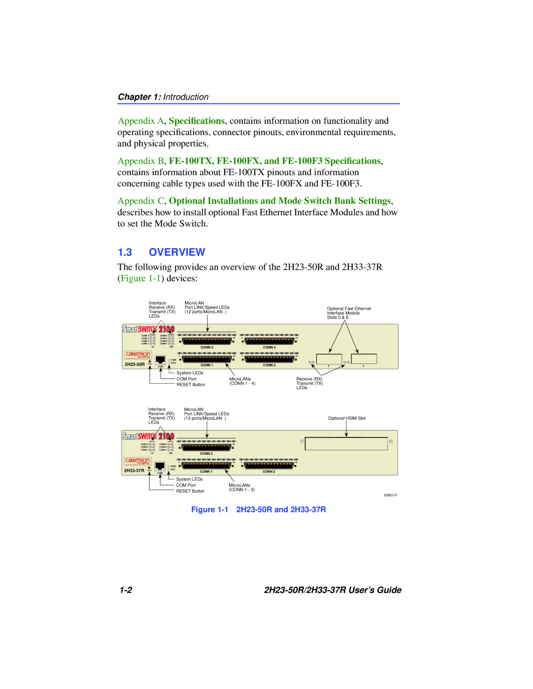
The following provides an overview of the
Interface |
| MicroLAN |
|
|
|
|
| |
Receive (RX) | Port LINK/Speed LEDs |
|
| Optional Fast Ethernet | ||||
Transmit (TX) | (12 ports/MicroLAN | ) |
|
| Interface Module |
| ||
LEDs |
|
|
|
|
| Slots 5 & 6 |
| |
|
|
|
|
|
|
|
| |
CONN 4 | CONN 4 | 1 |
| 12 | 1 |
| 12 |
|
CONN 3 | CONN 3 |
|
|
| ||||
CONN 2 | CONN 2 |
|
|
|
|
|
|
|
CONN 1 | CONN 1 |
|
|
|
|
|
|
|
10 |
| 100 | CONN 3 |
|
| CONN 4 |
|
|
|
| 1 |
| 12 | 1 |
| 12 |
|
|
| PWR |
|
|
|
|
|
|
COM | CPU | CONN 1 |
|
| CONN 2 | 5 | 6 | |
|
| System LEDs |
|
|
|
|
| |
|
| COM Port | MicroLANs |
| Receive (RX) |
| ||
|
| RESET Button | (CONN 1 - 4) |
| Transmit (TX) |
| ||
|
|
|
|
| LEDs |
| ||
|
|
|
|
|
|
|
| |
| Interface |
| MicroLAN |
|
|
| |
| Receive (RX) | Port LINK/Speed LEDs |
|
| |||
| Transmit (TX) | (12 ports/MicroLAN | ) |
|
| ||
| LEDs |
|
|
|
|
| |
CONN 3 | CONN 3 | 1 |
| 12 |
|
| |
CONN 2 | CONN 2 |
|
|
|
|
| |
CONN 1 | CONN 1 |
|
|
|
|
| |
| 10 |
| 100 | CONN 3 |
|
|
|
|
|
| 1 |
| 12 | 1 | 12 |
|
|
| PWR |
|
|
|
|
RESET | COM | CPU | CONN 1 |
|
| CONN 2 | |
|
|
| System LEDs |
|
|
| |
COM Port | MicroLANs |
RESET Button | (CONN 1 - 3) |
|
Optional HSIM Slot
Figure 1-1 2H23-50R and 2H33-37R
|
