Installing the Device
Installation
Rack mounting the
•Attaching the
•Rack mounting the device (attaching the mounting brackets and fastening the device to the rack)
Attaching the Strain-Relief Bracket
Attach the
1.Locate the
Do not attempt to attach the
!other than the
CAUTION | |
|
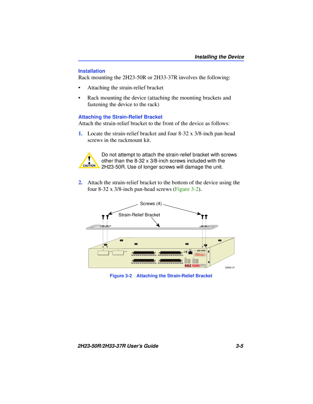
2.Attach the
Screws (4)
6 | 5 | |
|
|
|
| 2 CONN |
12 | 1 |
| 4 CONN |
12 | 1 |
1 CONN |
| COM | RESET |
| CPU | ||
|
| PWR |
|
12 | 1 |
|
|
3 CONN |
| 100 | 10 |
|
| 1 CONN | 1 CONN |
|
| 2 CONN | 2 CONN |
12 | 1 | 3 CONN | 3 CONN |
|
| 4 CONN | 4 CONN |
Figure 3-2 Attaching the Strain-Relief Bracket
|