Connecting to the Network
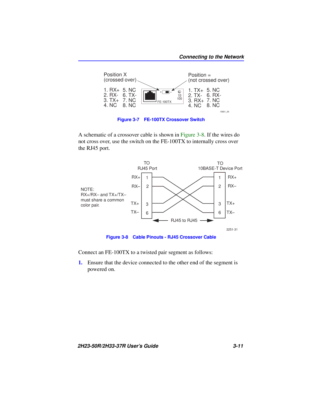
Position X (crossed over)
1.RX+ 5. NC
2.RX- 6. TX-
3.TX+ 7. NC
4.NC 8. NC
x |
|
|
| = |
|
|
|
|
|
10
100
Position =
(not crossed over)
1.TX+ 5. NC
2.TX- 6. RX-
3.RX+ 7. NC
4.NC 8. NC
16651_05
Figure 3-7 FE-100TX Crossover Switch
A schematic of a crossover cable is shown in Figure
NOTE:
RX+/RX– and TX+/TX– must share a common color pair.
| TO |
|
|
|
|
| TO |
| ||
RJ45 Port |
| |||||||||
RX+ |
|
|
|
|
|
|
|
|
| RX+ |
1 |
|
|
|
|
|
|
| 1 | ||
RX– | 2 |
|
|
|
|
|
|
| 2 | RX– |
TX+ | 3 |
|
|
|
|
|
|
| 3 | TX+ |
|
|
|
|
|
|
| ||||
|
|
|
|
|
|
| ||||
TX– | 6 |
|
|
|
|
|
|
| 6 | TX– |
|
|
|
|
| RJ45 to RJ45 |
|
|
|
| |
|
|
|
|
|
| |||||
|
|
|
|
|
|
|
| |||
Figure 3-8 Cable Pinouts - RJ45 Crossover Cable
Connect an
1.Ensure that the device connected to the other end of the segment is powered on.
|