Chapter 3: Installation
B |
|
|
|
|
| C |
|
|
|
|
|
|
|
| |
CONN 4 | CONN 4 | 1 | 12 | 1 |
| 12 |
|
CONN 3 | CONN 3 |
|
| ||||
CONN 2 | CONN 2 |
|
|
|
|
|
|
CONN 1 | CONN 1 |
|
|
|
|
|
|
10 |
| 100 | CONN 3 |
| CONN 4 |
|
|
A |
| 1 | 12 | 1 |
| 12 |
|
| PWR |
|
|
|
|
| |
| CPU |
|
|
|
|
| |
COM |
| CONN 1 |
| CONN 2 | 5 | 6 |
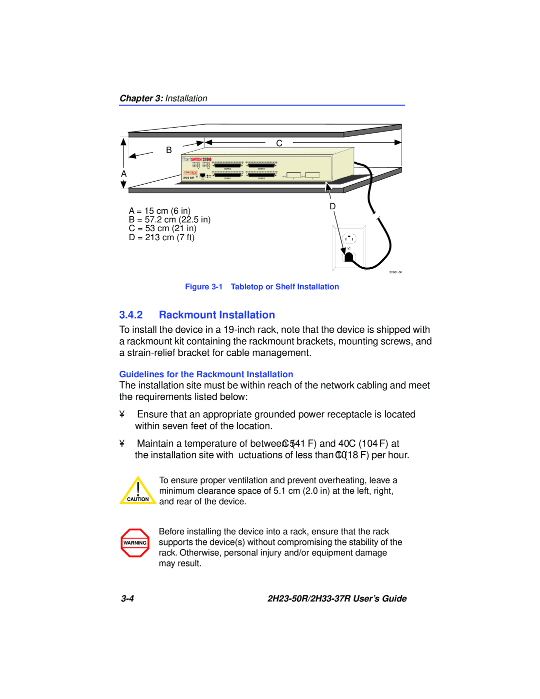
A = 15 cm (6 in)
B = 57.2 cm (22.5 in)
C = 53 cm (21 in)
D = 213 cm (7 ft)
D
Figure 3-1 Tabletop or Shelf Installation
3.4.2Rackmount Installation
To install the device in a
Guidelines for the Rackmount Installation
The installation site must be within reach of the network cabling and meet the requirements listed below:
•Ensure that an appropriate grounded power receptacle is located within seven feet of the location.
•Maintain a temperature of between 5°C (41°F) and 40°C (104°F) at the installation site with fluctuations of less than 10°C (18°F) per hour.
To ensure proper ventilation and prevent overheating, leave a
!minimum clearance space of 5.1 cm (2.0 in) at the left, right,
CAUTION | and rear of the device. |
|
WARNING
Before installing the device into a rack, ensure that the rack supports the device(s) without compromising the stability of the rack. Otherwise, personal injury and/or equipment damage may result.
|
