Chapter 3: Installation
Rack Mounting the Device
Proceed as follows to install the
1.Remove and discard the four cover screws (two from each side) located along the front edges of each side of the device.
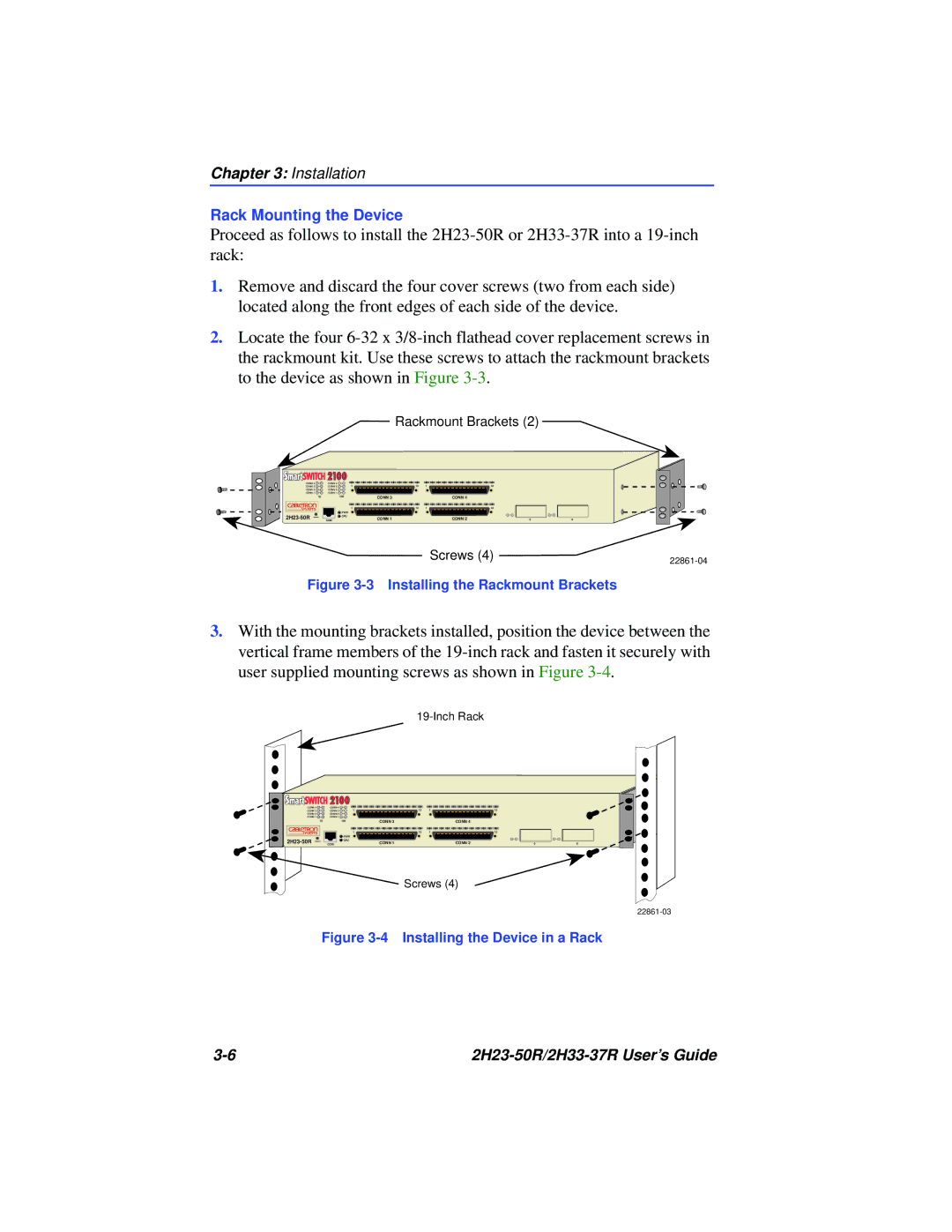
2.Locate the four
Rackmount Brackets (2)
CONN 4 | CONN 4 | 1 |
CONN 3 | CONN 3 | |
CONN 2 | CONN 2 |
|
CONN 1 | CONN 1 |
|
10100
1
![]() PWR
PWR
![]()
![]() CPU
CPU
COM
CONN 3
CONN 1
12 | 1 | 12 |
|
| CONN 4 |
12 | 1 | 12 |
|
| CONN 2 |
56
Screws (4) |
|
|
Figure 3-3 Installing the Rackmount Brackets
3.With the mounting brackets installed, position the device between the vertical frame members of the
CONN 4 | CONN 4 | 1 |
CONN 3 | CONN 3 | |
CONN 2 | CONN 2 |
|
CONN 1 | CONN 1 |
|
10 |
| 100 |
|
| 1 |
|
| PWR |
COM | CPU |
12 | 1 | 12 |
CONN 3 |
| CONN 4 |
12 | 1 | 12 |
CONN 1 |
| CONN 2 |
Screws (4)
|
|
|
5 | 6 | |
Figure 3-4 Installing the Device in a Rack
|