Chapter 4: Troubleshooting
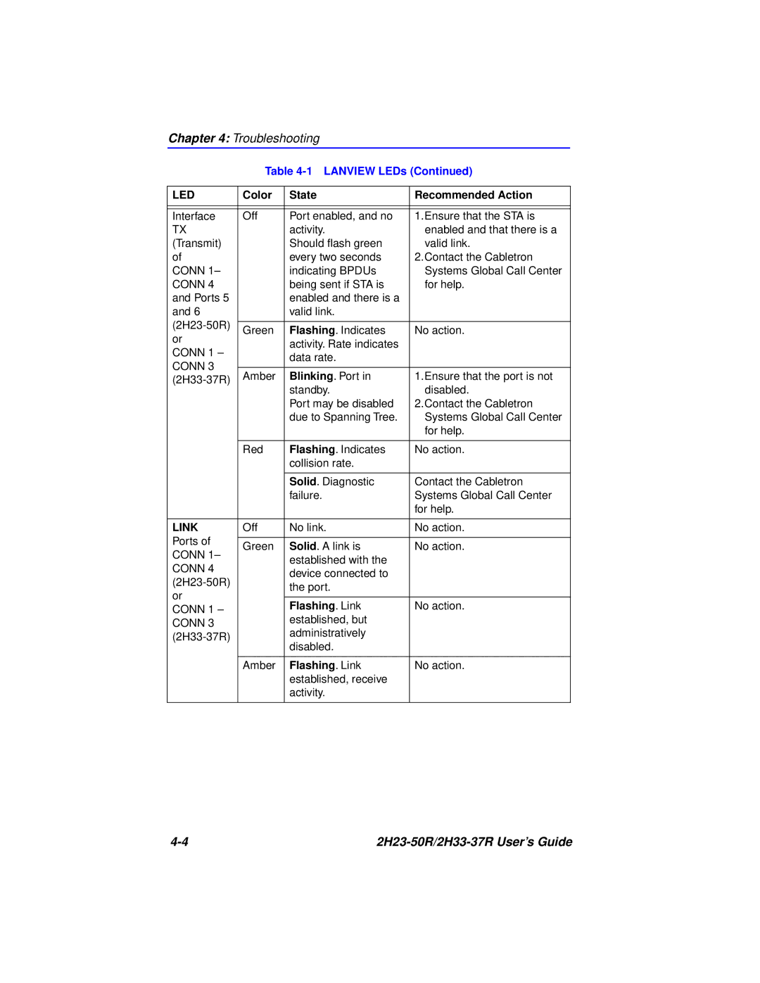
Table 4-1 LANVIEW LEDs (Continued)
LED | Color | State | Recommended Action | |
|
|
|
| |
|
|
|
| |
Interface | Off | Port enabled, and no | 1.Ensure that the STA is | |
TX |
| activity. | enabled and that there is a | |
(Transmit) |
| Should flash green | valid link. | |
of |
| every two seconds | 2.Contact the Cabletron | |
CONN 1– |
| indicating BPDUs | Systems Global Call Center | |
CONN 4 |
| being sent if STA is | for help. | |
and Ports 5 |
| enabled and there is a |
| |
and 6 |
| valid link. |
| |
|
|
| ||
Green | Flashing. Indicates | No action. | ||
or | ||||
| activity. Rate indicates |
| ||
CONN 1 – |
|
| ||
| data rate. |
| ||
CONN 3 |
|
| ||
|
|
| ||
Amber | Blinking. Port in | 1.Ensure that the port is not | ||
| standby. | disabled. | ||
|
| |||
|
| Port may be disabled | 2.Contact the Cabletron | |
|
| due to Spanning Tree. | Systems Global Call Center | |
|
|
| for help. | |
|
|
|
| |
| Red | Flashing. Indicates | No action. | |
|
| collision rate. |
| |
|
|
|
| |
|
| Solid. Diagnostic | Contact the Cabletron | |
|
| failure. | Systems Global Call Center | |
|
|
| for help. | |
|
|
|
| |
LINK | Off | No link. | No action. | |
Ports of |
|
|
| |
Green | Solid. A link is | No action. | ||
CONN 1– | ||||
| established with the |
| ||
CONN 4 |
|
| ||
| device connected to |
| ||
|
| |||
| the port. |
| ||
or |
|
| ||
|
|
| ||
| Flashing. Link | No action. | ||
CONN 1 – |
| |||
| established, but |
| ||
CONN 3 |
|
| ||
| administratively |
| ||
|
| |||
| disabled. |
| ||
|
|
| ||
|
|
|
| |
| Amber | Flashing. Link | No action. | |
|
| established, receive |
| |
|
| activity. |
| |
|
|
|
|
|